Three-phase Y and Δ configurations
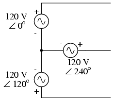
Initially we explored the idea of
three-phase power systems by connecting three voltage
sources together in what is commonly known as the "Y" (or
"star") configuration. This configuration of voltage sources
is characterized by a common connection point joining one
side of each source:
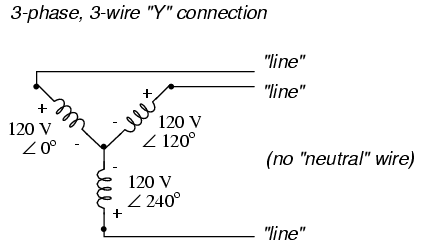
If we draw a circuit showing each voltage
source to be a coil of wire (alternator or transformer
winding) and do some slight rearranging, the "Y"
configuration becomes more obvious:

The three conductors leading away from the
voltage sources (windings) toward a load are typically
called lines, while the windings themselves are
typically called phases. In a Y-connected system,
there may or may not be a neutral wire attached at the
junction point in the middle, although it certainly helps
alleviate potential problems should one element of a
three-phase load fail open, as discussed earlier:
When we measure voltage and current in
three-phase systems, we need to be specific as to where
we're measuring. Line voltage refers to the amount of
voltage measured between any two line conductors in a
balanced three-phase system. With the above circuit, the
line voltage is roughly 208 volts. Phase voltage
refers to the voltage measured across any one component
(source winding or load impedance) in a balanced three-phase
source or load. For the circuit shown above, the phase
voltage is 120 volts. The terms line current and
phase current follow the same logic: the former
referring to current through any one line conductor, and the
latter to current through any one component.
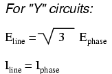
Y-connected sources and loads always have
line voltages greater than phase voltages, and line currents
equal to phase currents. If the Y-connected source or load
is balanced, the line voltage will be equal to the phase
voltage times the square root of 3:
However, the "Y" configuration is not the
only valid one for connecting three-phase voltage source or
load elements together. Another configuration is known as
the "Delta," for its geometric resemblance to the Greek
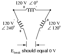
letter of the same name (Δ). Take close notice of the
polarity for each winding in the drawing below:

At first glance it seems as though three
voltage sources like this would create a short-circuit,
electrons flowing around the triangle with nothing but the
internal impedance of the windings to hold them back. Due to
the phase angles of these three voltage sources, however,
this is not the case.
One quick check of this is to use
Kirchhoff's Voltage Law to see if the three voltages around
the loop add up to zero. If they do, then there will be no
voltage available to push current around and around that
loop, and consequently there will be no circulating current.
Starting with the top winding and progressing
counter-clockwise, our KVL expression looks something like
this:
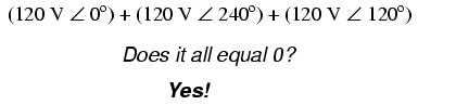
Indeed, if we add these three vector
quantities together, they do add up to zero. Another way to
verify the fact that these three voltage sources can be
connected together in a loop without resulting in
circulating currents is to open up the loop at one junction
point and calculate voltage across the break:
Starting with the right winding (120 V ∠ 120o)
and progressing counter-clockwise, our KVL equation looks
like this:
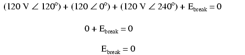
Sure enough, there will be zero voltage
across the break, telling us that no current will circulate
within the triangular loop of windings when that connection
is made complete.
Having established that a Δ-connected
three-phase voltage source will not burn itself to a crisp
due to circulating currents, we turn to its practical use as
a source of power in three-phase circuits. Because each pair
of line conductors is connected directly across a single
winding in a Δ circuit, the line voltage will be equal to
the phase voltage. Conversely, because each line conductor
attaches at a node between two windings, the line current
will be the vector sum of the two joining phase currents.
Not surprisingly, the resulting equations for a Δ
configuration are as follows:

Let's see how this works in an example
circuit:

With each load resistance receiving 120
volts from its respective phase winding at the source, the
current in each phase of this circuit will be 83.33 amps:

So, the each line current in this
three-phase power system is equal to 144.34 amps,
substantially more than the line currents in the Y-connected
system we looked at earlier. One might wonder if we've lost
all the advantages of three-phase power here, given the fact
that we have such greater conductor currents, necessitating
thicker, more costly wire. The answer is no. Although this
circuit would require three number 1 gage copper conductors
(at 1000 feet of distance between source and load this
equates to a little over 750 pounds of copper for the whole
system), it is still less than the 1000+ pounds of copper
required for a single-phase system delivering the same power
(30 kW) at the same voltage (120 volts
conductor-to-conductor).
One distinct advantage of a Δ-connected
system is its lack of a neutral wire. With a Y-connected
system, a neutral wire was needed in case one of the phase
loads were to fail open (or be turned off), in order to keep
the phase voltages at the load from changing. This is not
necessary (or even possible!) in a Δ-connected circuit. With
each load phase element directly connected across a
respective source phase winding, the phase voltage will be
constant regardless of open failures in the load elements.
Perhaps the greatest advantage of the
Δ-connected source is its fault tolerance. It is possible
for one of the windings in a Δ-connected three-phase source
to fail open without affecting load voltage or current!
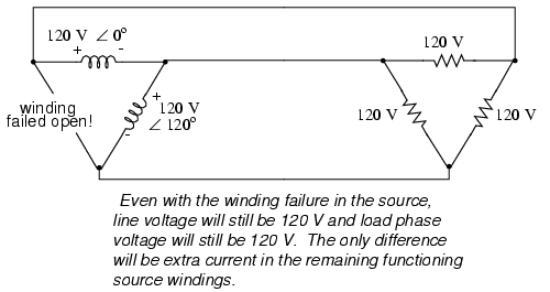
The only consequence of a source winding
failing open for a Δ-connected source is increased phase
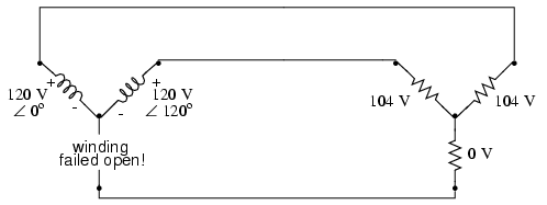
current in the remaining windings. Compare this fault
tolerance with a Y-connected system suffering an open source
winding:
With a Δ-connected load, two of the
resistances suffer reduced voltage while one remains at the
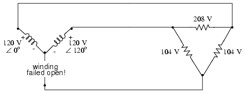
original line voltage, 208. A Y-connected load suffers an
even worse fate with the same winding failure in a
Y-connected source:
In this case, two load resistances suffer
reduced voltage while the third loses supply voltage
completely! For this reason, Δ-connected sources are
preferred for reliability. However, if dual voltages are
needed (e.g. 120/208) or preferred for lower line currents,
Y-connected systems are the configuration of choice.
-
REVIEW:
-
The conductors connected to the three
points of a three-phase source or load are called lines.
-
The three components comprising a
three-phase source or load are called phases.
-
Line voltage is the voltage
measured between any two lines in a three-phase circuit.
-
Phase voltage is the voltage
measured across a single component in a three-phase source
or load.
-
Line current is the current through
any one line between a three-phase source and load.
-
Phase current is the current
through any one component comprising a three-phase source
or load.
-
In balanced "Y" circuits, line voltage is
equal to phase voltage times the square root of 3, while
line current is equal to phase current.
-
-
In balanced Δ circuits, line voltage is
equal to phase voltage, while line current is equal to
phase current times the square root of 3.
-
-
Δ-connected three-phase voltage sources
give greater reliability in the event of winding failure
than Y-connected sources. However, Y-connected sources can
deliver the same amount of power with less line current
than Δ-connected sources.
|
