|
This page is going to describe the
parts, schematic, software, and some tips on using
Infrared for object detection. The parts used are
typically the same parts found in most consumer
electronic remote controls, and are widely available. If
you have an old TV or other IR remote device, you have
the makings of a nice IR detection system.
The Parts
The two basic parts for working with IR
are the emitter and the detector. The emitter is
typically an LED that emits near-infrared light. A
typical wavelength is 880nm, which is just beyond the
human eyes ability to see. Many suppliers, new and
surplus, can provide you with sources of LED emitters. A
typical IR detection system will use two emitters. By
controlling when the emitters are active, the detection
system can determine simple directional information:
Left, Right, or Front.
There are several types of detectors for
IR light. There are photo-diodes, photo-transistors, and
a couple others. Usually, you buy IR emitter/detector
pairs, which are tuned for each other. This is
recommended when buying surplus, since chances are
someone has verified they work together.
The other important detector for working
with IR is a detector module, such as the Sharp GP1U5
(also the G1U52X) module. This module contains the IR
detector and a small circuit that detects a 40khz
modulation (i.e. the IR light is flashing on and off at
about 40khz). The nice part about using a modulated
light is the ability to reject noisy light signals. The
world is full of light sources. Being able to detect a
certain quality of a light, such as flashing at 40khz,
means you can filter out much of the light you don't
want.
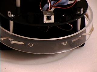
The
components of the IR detection system
The above photo shows these parts
installed on the front of a robot. The Sharp IR detector
module is the square box at the top of the frame, and
the emitters are enclosed in aluminum tubes near the
bottom.
To use the Sharp IR detection module,
you need to have a circuit that can flash the light at
40khz, which is 40,000 a second (pretty fast!). This is
called modulation. The circuit that does modulation is
called an oscillator, and I have shown one below.
A simple 40khz modulation circuit.
The above circuit is an interesting one
to look at. It uses a single 74HC04 (inverter) in
several ways that you don't normally see, especially all
at once. Lets take a quick tour.
There are three major parts to the
circuit. The center (U1:A and U1:B plus discrete
components) forms a feedback oscillator. If you follow
the flow of the logic gates, you see that the output of
A is fed into the input of B, which is fed to the input
of A. Now, there is a gate propagation delay factor that
causes this circuit to continuously flip states. The
important state is the output of gate U1:B, which is fed
to the driver gates. The resistors and capacitor in the
circuit are there to regulate the frequency at which
this circuit feeds back into itself. Resistor R2 can be
used to adjust the frequency of this circuit. The Sharp
detector is fairly forgiving about the exact modulation
frequency, but getting it as close as possible to 40khz
is recommended. Note that the above circuit is tuned to
work with the 74HC04, and is known NOT TO WORK with the
7404, 74LS04, and other TTL versions. Do yourself a
favor and get the real thing.
The output from the oscillator is sent
through two buffers. Here the gates act to isolate the
oscillator section from the IR emitter section. The
buffers also act as current sources for the IR emitters.
It is important to isolate the oscillator from the
LED's, since the timing would be affected by the
particular types of LED you use.
The final gates are the U1:C and U1:D
gates. These are the control lines that you would
connect to the output ports of the CPU. They act to
buffer the CPU from the current requirements of the
LED's.
The interface to the CPU is done through
pins 5 and 9 in the above circuit (gates C and D). These
control when the emitters turn on. The only other
variable is the resistor R2, which should only require
initial adjustment to get the correct frequency.
The Detector module is simple to wire
up. The connections are to power, ground, and the output
signal. The output from the sharp detector is a digital
signal.
Notice that R5 acts as a pull-up
resistor, similar to other digital inputs. Capacitor C1
acts as a bypass capacitor. Another unusual connection
is between ground and the case. Most of the Sharp
modules are intended to be mounted on a circuit board.
It expects the case to be grounded. Be sure to make a
electrical connection between ground and the case by
soldering a wire directly to the metal housing |
