|
A truth table is a complete enumeration of all possible
combinations of input values, each one with its associated output
value.
When used to describe an existing circuit, output values are (of
course) either 0 or 1. Suppose for
instance that we wish to make a truth table for the following
circuit:
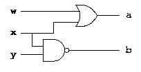
All we need to do to establish a truth table for this circuit is
to compute the output value for the circuit for each possible
combination of input values. We obtain the following truth table:
  w x y | a b
  -----------
  0 0 0 | 0 1
  0 0 1 | 0 1
  0 1 0 | 1 1
  0 1 1 | 1 0
  1 0 0 | 1 1
  1 0 1 | 1 1
  1 1 0 | 1 1
  1 1 1 | 1 0
When used as a specification for a circuit, a table may
have some output values that are not specified, perhaps because the
corresponding combination of input values can never occur in the
particular application. We can indicate such unspecified output
values with a dash -.
For instance, let us suppose we want a circuit of four inputs,
interpreted as two nonnegative binary integers of two binary digits
each, and two outputs, interpreted as the nonnegative binary integer
giving the quotient between the two input numbers. Since division is
not defined when the denominator is zero, we do not care what the
output value is in this case. Of the sixteen entries in the truth
table, four have a zero denominator. Here is the truth table:
  x1 x0 y1 y0 | z1 z0
  -------------------
   0  0  0  0 | -  -
   0  0  0  1 | 0  0
   0  0  1  0 | 0  0
   0  0  1  1 | 0  0
   0  1  0  0 | -  -
   0  1  0  1 | 0  1
   0  1  1  0 | 0  0
   0  1  1  1 | 0  0
   1  0  0  0 | -  -
   1  0  0  1 | 1  0
   1  0  1  0 | 0  1
   1  0  1  1 | 0  0
   1  1  0  0 | -  -
   1  1  0  1 | 1  1
   1  1  1  0 | 0  1
   1  1  1  1 | 0  1
Unspecified output values like this can greatly decrease the
number of circuits necessary to build the circuit. The reason is
simple: when we are free to choose the output value in a particular
situation, we choose the one that gives the fewest total number of
gates.
For the purpose of this course, we don't care about minimality.
It might be conceptually advantageous still to indicate outputs with
arbitrary values. |


