In designing digital circuits, the designer
often begins with a truth table describing what the circuit should do. The
design task is largely to determine what type of circuit will perform the
function described in the truth table. While some people seem to have a
natural ability to look at a truth table and immediately envision the
necessary logic gate or relay logic circuitry for the task, there are
procedural techniques available for the rest of us. Here, Boolean algebra
proves its utility in a most dramatic way.
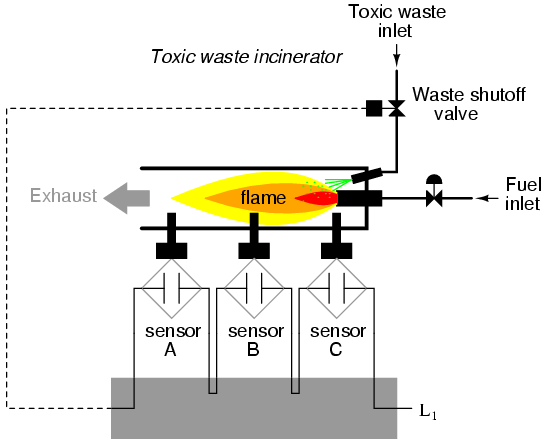
To illustrate this procedural method, we should begin with a realistic
design problem. Suppose we were given the task of designing a flame
detection circuit for a toxic waste incinerator. The intense heat of the
fire is intended to neutralize the toxicity of the waste introduced into the
incinerator. Such combustion-based techniques are commonly used to
neutralize medical waste, which may be infected with deadly viruses or
bacteria:
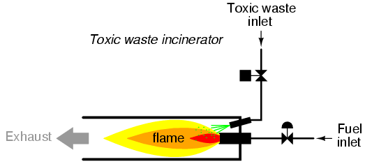
So long as a flame is maintained in the incinerator, it is safe to inject
waste into it to be neutralized. If the flame were to be extinguished,
however, it would be unsafe to continue to inject waste into the combustion
chamber, as it would exit the exhaust un-neutralized, and pose a health
threat to anyone in close proximity to the exhaust. What we need in this
system is a sure way of detecting the presence of a flame, and permitting
waste to be injected only if a flame is "proven" by the flame detection
system.
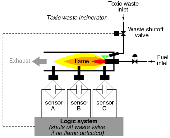
Several different flame-detection technologies exist: optical (detection
of light), thermal (detection of high temperature), and electrical
conduction (detection of ionized particles in the flame path), each one with
its unique advantages and disadvantages. Suppose that due to the high degree
of hazard involved with potentially passing un-neutralized waste out the
exhaust of this incinerator, it is decided that the flame detection system
be made redundant (multiple sensors), so that failure of a single sensor
does not lead to an emission of toxins out the exhaust. Each sensor comes
equipped with a normally-open contact (open if no flame, closed if flame
detected) which we will use to activate the inputs of a logic system:
Our task, now, is to design the circuitry of the logic system to open the
waste valve if and only if there is good flame proven by the sensors. First,
though, we must decide what the logical behavior of this control system
should be. Do we want the valve to be opened if only one out of the three
sensors detects flame? Probably not, because this would defeat the purpose
of having multiple sensors. If any one of the sensors were to fail in such a
way as to falsely indicate the presence of flame when there was none, a
logic system based on the principle of "any one out of three sensors showing
flame" would give the same output that a single-sensor system would with the
same failure. A far better solution would be to design the system so that
the valve is commanded to open if any only if all three sensors
detect a good flame. This way, any single, failed sensor falsely showing
flame could not keep the valve in the open position; rather, it would
require all three sensors to be failed in the same manner -- a highly
improbable scenario -- for this dangerous condition to occur.
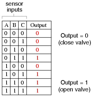
Thus, our truth table would look like this:
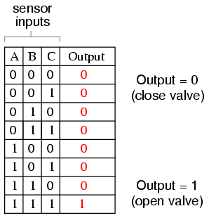
It does not require much insight to realize that this functionality could
be generated with a three-input AND gate: the output of the circuit will be
"high" if and only if input A AND input B AND input C are all
"high:"
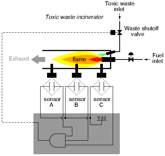
If using relay circuitry, we could create this AND function by wiring
three relay contacts in series, or simply by wiring the three sensor
contacts in series, so that the only way electrical power could be sent to
open the waste valve is if all three sensors indicate flame:
While this design strategy maximizes safety, it makes the system very
susceptible to sensor failures of the opposite kind. Suppose that one of the
three sensors were to fail in such a way that it indicated no flame when
there really was a good flame in the incinerator's combustion chamber. That
single failure would shut off the waste valve unnecessarily, resulting in
lost production time and wasted fuel (feeding a fire that wasn't being used
to incinerate waste).
It would be nice to have a logic system that allowed for this kind of
failure without shutting the system down unnecessarily, yet still provide
sensor redundancy so as to maintain safety in the event that any single
sensor failed "high" (showing flame at all times, whether or not there was
one to detect). A strategy that would meet both needs would be a "two out of
three" sensor logic, whereby the waste valve is opened if at least two out
of the three sensors show good flame. The truth table for such a system
would look like this:
Here, it is not necessarily obvious what kind of logic circuit would
satisfy the truth table. However, a simple method for designing such a
circuit is found in a standard form of Boolean expression called the
Sum-Of-Products, or SOP, form. As you might suspect, a
Sum-Of-Products Boolean expression is literally a set of Boolean terms added
(summed) together, each term being a multiplicative (product)
combination of Boolean variables. An example of an SOP expression would be
something like this: ABC + BC + DF, the sum of products "ABC," "BC," and
"DF."
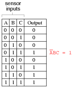
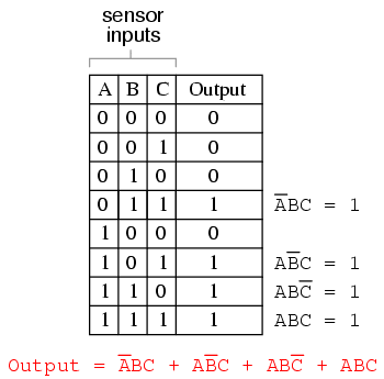
Sum-Of-Products expressions are easy to generate from truth tables. All
we have to do is examine the truth table for any rows where the output is
"high" (1), and write a Boolean product term that would equal a value of 1
given those input conditions. For instance, in the fourth row down in the
truth table for our two-out-of-three logic system, where A=0, B=1, and C=1,
the product term would be A'BC, since that term would have a value of 1 if
and only if A=0, B=1, and C=1:
Three other rows of the truth table have an output value of 1, so those
rows also need Boolean product expressions to represent them:
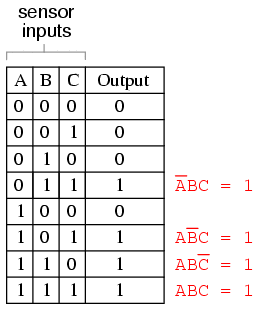
Finally, we join these four Boolean product expressions together by
addition, to create a single Boolean expression describing the truth table
as a whole:
Now that we have a Boolean Sum-Of-Products expression for the truth
table's function, we can easily design a logic gate or relay logic circuit
based on that expression:

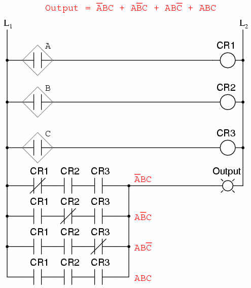
Unfortunately, both of these circuits are quite complex, and could
benefit from simplification. Using Boolean algebra techniques, the
expression may be significantly simplified:
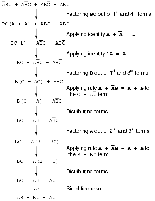
As a result of the simplification, we can now build much simpler logic
circuits performing the same function, in either gate or relay form:
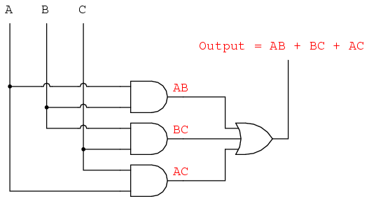
Either one of these circuits will adequately perform the task of
operating the incinerator waste valve based on a flame verification from two
out of the three flame sensors. At minimum, this is what we need to have a
safe incinerator system. We can, however, extend the functionality of the
system by adding to it logic circuitry designed to detect if any one of the
sensors does not agree with the other two.
If all three sensors are operating properly, they should detect flame
with equal accuracy. Thus, they should either all register "low" (000: no
flame) or all register "high" (111: good flame). Any other output
combination (001, 010, 011, 100, 101, or 110) constitutes a disagreement
between sensors, and may therefore serve as an indicator of a potential
sensor failure. If we added circuitry to detect any one of the six "sensor
disagreement" conditions, we could use the output of that circuitry to
activate an alarm. Whoever is monitoring the incinerator would then exercise
judgment in either continuing to operate with a possible failed sensor
(inputs: 011, 101, or 110), or shut the incinerator down to be absolutely
safe. Also, if the incinerator is shut down (no flame), and one or more of
the sensors still indicates flame (001, 010, 011, 100, 101, or 110) while
the other(s) indicate(s) no flame, it will be known that a definite sensor
problem exists.
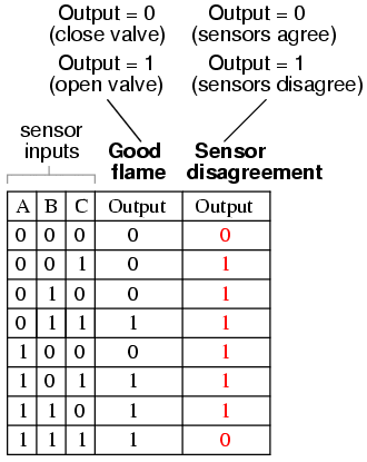
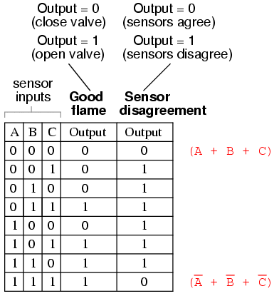
The first step in designing this "sensor disagreement" detection circuit
is to write a truth table describing its behavior. Since we already have a
truth table describing the output of the "good flame" logic circuit, we can
simply add another output column to the table to represent the second
circuit, and make a table representing the entire logic system:
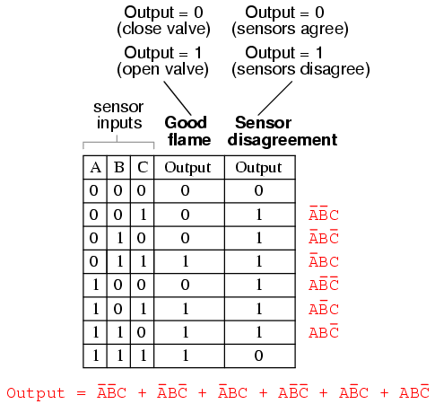
While it is possible to generate a Sum-Of-Products expression for this
new truth table column, it would require six terms, of three variables each!
Such a Boolean expression would require many steps to simplify, with a large
potential for making algebraic errors:
An alternative to generating a Sum-Of-Products expression to account for
all the "high" (1) output conditions in the truth table is to generate a
Product-Of-Sums, or POS, expression, to account for all the "low"
(0) output conditions instead. Being that there are much fewer instances of
a "low" output in the last truth table column, the resulting Product-Of-Sums
expression should contain fewer terms. As its name suggests, a
Product-Of-Sums expression is a set of added terms (sums), which are
multiplied (product) together. An example of a POS expression would
be (A + B)(C + D), the product of the sums "A + B" and "C + D".
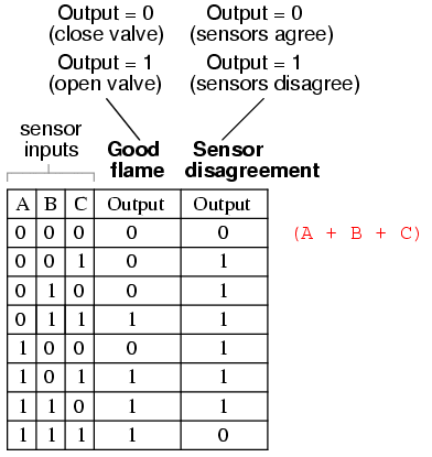
To begin, we identify which rows in the last truth table column have
"low" (0) outputs, and write a Boolean sum term that would equal 0 for that
row's input conditions. For instance, in the first row of the truth table,
where A=0, B=0, and C=0, the sum term would be (A + B + C), since that term
would have a value of 0 if and only if A=0, B=0, and C=0:
Only one other row in the last truth table column has a "low" (0) output,
so all we need is one more sum term to complete our Product-Of-Sums
expression. This last sum term represents a 0 output for an input condition
of A=1, B=1 and C=1. Therefore, the term must be written as (A' + B'+ C'),
because only the sum of the complemented input variables would equal
0 for that condition only:
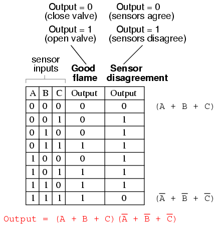
The completed Product-Of-Sums expression, of course, is the
multiplicative combination of these two sum terms:
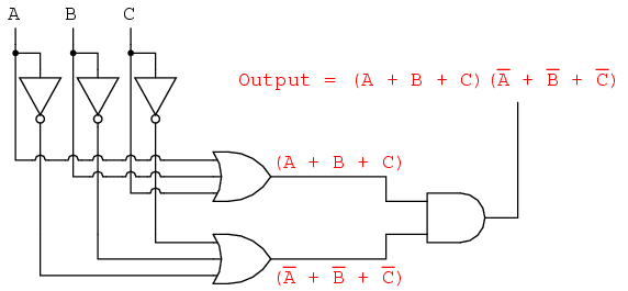
Whereas a Sum-Of-Products expression could be implemented in the form of
a set of AND gates with their outputs connecting to a single OR gate, a
Product-Of-Sums expression can be implemented as a set of OR gates feeding
into a single AND gate:
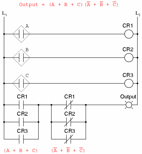
Correspondingly, whereas a Sum-Of-Products expression could be
implemented as a parallel collection of series-connected relay contacts, a
Product-Of-Sums expression can be implemented as a series collection of
parallel-connected relay contacts:
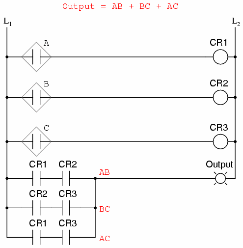
The previous two circuits represent different versions of the "sensor
disagreement" logic circuit only, not the "good flame" detection circuit(s).
The entire logic system would be the combination of both "good flame" and
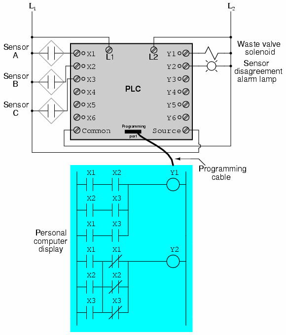
"sensor disagreement" circuits, shown on the same diagram.
Implemented in a Programmable Logic Controller (PLC), the entire logic
system might resemble something like this:
As you can see, both the Sum-Of-Products and Products-Of-Sums standard
Boolean forms are powerful tools when applied to truth tables. They allow us
to derive a Boolean expression -- and ultimately, an actual logic circuit --
from nothing but a truth table, which is a written specification for what we
want a logic circuit to do. To be able to go from a written specification to
an actual circuit using simple, deterministic procedures means that it is
possible to automate the design process for a digital circuit. In other
words, a computer could be programmed to design a custom logic circuit from
a truth table specification! The steps to take from a truth table to the
final circuit are so unambiguous and direct that it requires little, if any,
creativity or other original thought to execute them.
REVIEW: Sum-Of-Products, or SOP, Boolean expressions may be
generated from truth tables quite easily, by determining which rows of the
table have an output of 1, writing one product term for each row, and
finally summing all the product terms. This creates a Boolean expression
representing the truth table as a whole. Sum-Of-Products expressions lend themselves well to implementation as
a set of AND gates (products) feeding into a single OR gate (sum). Product-Of-Sums, or POS, Boolean expressions may also be
generated from truth tables quite easily, by determining which rows of the
table have an output of 0, writing one sum term for each row, and finally
multiplying all the sum terms. This creates a Boolean expression
representing the truth table as a whole. Product-Of-Sums expressions lend themselves well to implementation as
a set of OR gates (sums) feeding into a single AND gate (product).
|
