It is sometimes desirable to have a logic gate that
provides both inverted and non-inverted outputs. For example, a single-input
gate that is both a buffer and an inverter, with a separate output terminal
for each function. Or, a two-input gate that provides both the AND and the
NAND functions in a single circuit. Such gates do exist and they are
referred to as complementary output gates.
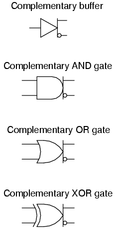
The general symbology for such a gate is the basic gate figure with a bar
and two output lines protruding from it. An array of complementary gate
symbols is shown in the following illustration:
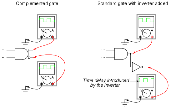
Complementary gates are especially useful in "crowded" circuits where
there may not be enough physical room to mount the additional integrated
circuit chips necessary to provide both inverted and noninverted outputs
using standard gates and additional inverters. They are also useful in
applications where a complementary output is necessary from a gate, but the
addition of an inverter would introduce an unwanted time lag in the inverted
output relative to the noninverted output. The internal circuitry of
complemented gates is such that both inverted and noninverted outputs change
state at almost exactly the same time:
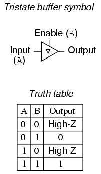
Another type of special gate output is called tristate, because it
has the ability to provide three different output modes: current sinking
("low" logic level), current sourcing ("high"), and floating ("high-Z," or
high-impedance). Tristate outputs are usually found as an optional
feature on buffer gates. Such gates require an extra input terminal to
control the "high-Z" mode, and this input is usually called the enable.
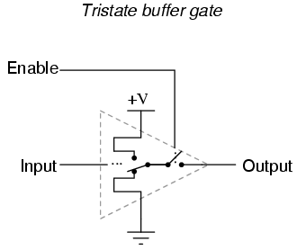
With the enable input held "high" (1), the buffer acts like an ordinary
buffer with a totem pole output stage: it is capable of both sourcing and
sinking current. However, the output terminal floats (goes into "high-Z"
mode) if ever the enable input is grounded ("low"), regardless of the data
signal's logic level. In other words, making the enable input terminal "low"
(0) effectively disconnects the gate from whatever its output is
wired to so that it can no longer have any effect.
Tristate buffers are marked in schematic diagrams by a triangle character
within the gate symbol like this:
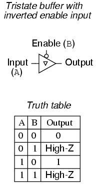
Tristate buffers are also made with inverted enable inputs. Such a gate
acts normal when the enable input is "low" (0) and goes into high-Z output
mode when the enable input is "high" (1):
One special type of gate known as the bilateral switch uses
gate-controlled MOSFET transistors acting as on/off switches to switch
electrical signals, analog or digital. The "on" resistance of such a switch
is in the range of several hundred ohms, the "off" resistance being in the
range of several hundred mega-ohms.
Bilateral switches appear in schematics as SPST (Single-Pole,
Single-Throw) switches inside of rectangular boxes, with a control terminal
on one of the box's long sides:
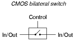
A bilateral switch might be best envisioned as a solid-state
(semiconductor) version of an electromechanical relay: a signal-actuated
switch contact that may be used to conduct virtually any type of electric
signal. Of course, being solid-state, the bilateral switch has none of the
undesirable characteristics of electromechanical relays, such as contact
"bouncing," arcing, slow speed, or susceptibility to mechanical vibration.
Conversely, though, they are rather limited in their current-carrying
ability. Additionally, the signal conducted by the "contact" must not exceed
the power supply "rail" voltages powering the bilateral switch circuit.
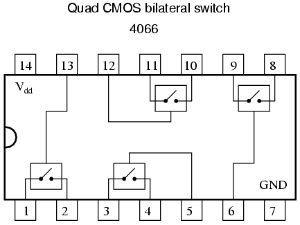
Four bilateral switches are packaged inside the popular model "4066"
integrated circuit:
REVIEW: Complementary gates provide both inverted and noninverted
output signals, in such a way that neither one is delayed with respect to
the other. Tristate gates provide three different output states: high,
low, and floating (High-Z). Such gates are commanded into their
high-impedance output modes by a separate input terminal called the
enable. Bilateral switches are MOSFET circuits providing on/off
switching for a variety of electrical signal types (analog and digital),
controlled by logic level voltage signals. In essence, they are
solid-state relays with very low current-handling ability.
|
