Make your own multimeter
PARTS AND MATERIALS
-
Sensitive meter movement (Radio Shack
catalog # 22-410)
-
Selector switch, single-pole, multi-throw,
break-before-make (Radio Shack catalog # 275-1386 is a
2-pole, 6-position unit that works well)
-
Multi-turn potentiometers, PCB mount
(Radio Shack catalog # 271-342 and 271-343 are 15-turn, 1
kΩ and 10 kΩ "trimmer" units, respectively)
-
Assorted resistors, preferably
high-precision metal film or wire-wound types (Radio Shack
catalog # 271-309 is an assortment of metal-film
resistors, +/- 1% tolerance)
-
Plastic or metal mounting box
-
Three "banana" jack style binding posts,
or other terminal hardware, for connection to
potentiometer circuit (Radio Shack catalog # 274-662 or
equivalent)
The most important and expensive component
in a meter is the movement: the actual
needle-and-scale mechanism whose task it is to translate an
electrical current into mechanical displacement where it may
be visually interpreted. The ideal meter movement is
physically large (for ease of viewing) and as sensitive as
possible (requires minimal current to produce full-scale
deflection of the needle). High-quality meter movements are
expensive, but Radio Shack carries some of acceptable
quality that are reasonably priced. The model recommended in
the parts list is sold as a voltmeter with a 0-15 volt
range, but is actually a milliammeter with a range
("multiplier") resistor included separately.
It may be cheaper to purchase an inexpensive
analog meter and disassemble it for the meter movement
alone. Although the thought of destroying a working
multimeter in order to have parts to make your own may sound
counter-productive, the goal here is learning, not
meter function.
I cannot specify resistor values for this
experiment, as these depend on the particular meter movement
and measurement ranges chosen. Be sure to use high-precision
fixed-value resistors rather than carbon-composition
resistors. Even if you happen to find carbon-composition
resistors of just the right value(s), those values will
change or "drift" over time due to aging and temperature
fluctuations. Of course, if you don't care about the
long-term stability of this meter but are building it just
for the learning experience, resistor precision matters
little.
CROSS-REFERENCES
Lessons In Electric Circuits, Volume
1, chapter 8: "DC Metering Circuits"
LEARNING OBJECTIVES
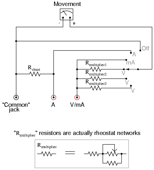
SCHEMATIC DIAGRAM
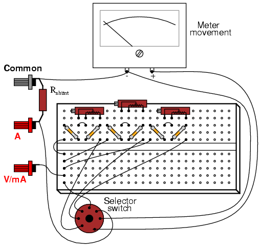
ILLUSTRATION
INSTRUCTIONS
First, you need to determine the
characteristics of your meter movement. Most important is to
know the full scale deflection in milliamps or
microamps. To determine this, connect the meter movement, a
potentiometer, battery, and digital ammeter in series.
Adjust the potentiometer until the meter movement is
deflected exactly to full-scale. Read the ammeter's display
to find the full-scale current value:

Be very careful not to apply too much
current to the meter movement, as movements are very
sensitive devices and easily damaged by overcurrent. Most
meter movements have full-scale deflection current ratings
of 1 mA or less, so choose a potentiometer value high enough
to limit current appropriately, and begin testing with the
potentiometer turned to maximum resistance. The lower the
full-scale current rating of a movement, the more sensitive
it is.
After determining the full-scale current
rating of your meter movement, you must accurately measure
its internal resistance. To do this, disconnect all
components from the previous testing circuit and connect
your digital ohmmeter across the meter movement terminals.
Record this resistance figure along with the full-scale
current figure obtained in the last procedure.
Perhaps the most challenging portion of this
project is determining the proper range resistance values
and implementing those values in the form of rheostat
networks. The calculations are outlined in chapter 8 of
volume 1 ("Metering Circuits"), but an example is given
here. Suppose your meter movement had a full-scale rating of
1 mA and an internal resistance of 400 Ω. If we wanted to
determine the necessary range resistance ("Rmultiplier")
to give this movement a range of 0 to 15 volts, we would
have to divide 15 volts (total applied voltage) by 1 mA
(full-scale current) to obtain the total probe-to-probe
resistance of the voltmeter (R=E/I). For this example, that
total resistance is 15 kΩ. From this total resistance
figure, we subtract the movement's internal resistance,
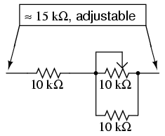
leaving 14.6 kΩ for the range resistor value. A simple
rheostat network to produce 14.6 kΩ (adjustable) would be a
10 kΩ potentiometer in parallel with a 10 kΩ fixed resistor,
all in series with another 10 kΩ fixed resistor:
One position of the selector switch directly
connects the meter movement between the black Common
binding post and the red V/mA binding post. In this
position, the meter is a sensitive ammeter with a range
equal to the full-scale current rating of the meter
movement. The far clockwise position of the switch
disconnects the positive (+) terminal of the movement from
either red binding post and shorts it directly to the
negative (-) terminal. This protects the meter from
electrical damage by isolating it from the red test probe,
and it "dampens" the needle mechanism to further guard
against mechanical shock.
The shunt resistor (Rshunt)
necessary for a high-current ammeter function needs to be a
low-resistance unit with a high power dissipation. You will
definitely not be using any 1/4 watt resistors for
this, unless you form a resistance network with several
smaller resistors in parallel combination. If you plan on
having an ammeter range in excess of 1 amp, I recommend
using a thick piece of wire or even a skinny piece of sheet
metal as the "resistor," suitably filed or notched to
provide just the right amount of resistance.
To calibrate a home-made shunt resistor, you
will need to connect the your multimeter assembly to a
calibrated source of high current, or a high-current source
in series with a digital ammeter for reference. Use a small
metal file to shave off shunt wire thickness or to notch the
sheet metal strip in small, careful amounts. The resistance
of your shunt will increase with every stroke of the file,
causing the meter movement to deflect more strongly.
Remember that you can always approach the exact value in
slower and slower steps (file strokes), but you cannot go
"backward" and decrease the shunt resistance!
Build the multimeter circuit on a breadboard
first while determining proper range resistance values, and
perform all calibration adjustments there. For final
construction, solder the components on to a printed-circuit
board. Radio Shack sells printed circuit boards that have
the same layout as a breadboard, for convenience (catalog #
276-170). Feel free to alter the component layout from what
is shown.
I strongly recommend that you mount the
circuit board and all components in a sturdy box, so that
the meter is durably finished. Despite the limitations of
this multimeter (no resistance function, inability to
measure alternating current, and lower precision than most
purchased analog multimeters), it is an excellent project to
assist learning fundamental instrument principles and
circuit function. A far more accurate and versatile
multimeter may be constructed using many of the same parts
if an amplifier circuit is added to it, so save the parts
and pieces for a later experiment!
|
