This tutorial shows how to
set up a system for collecting data through a
computers serial port. It uses an ADC0804 chip
to convert from analog to digital, an
AT89C2051 microcontroller to control the
ADC0804 and send data to the PC, and a MAX232CPE
chip to convert the signals from and to RS232
levels for sending and receiving from the PC.
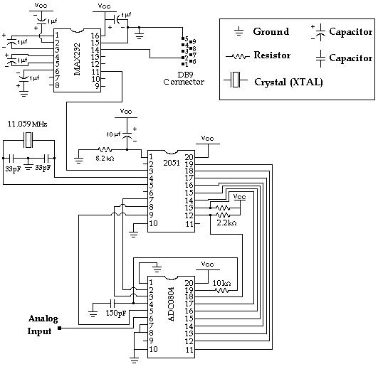
Refer to the diagram
below as you go through the individual steps in
building the circuit.
Step 1.)
Analog to Digital Conversion - The ADC0804 IC
The
easiest way to do analog to digital conversion
is to use an IC such as the ADC0804 that does
the work for you. The analog voltage is applied
to pin 6 and the result is available at pins 11
through 18. We will
connect pin 1 (Chip Select) to ground so that
the chip is always enabled. (If you
wanted to use more than one ADC you could use
this pin to control which chip is currently
enabled).
Connect pin 7 (Vin - ) to
ground.
The ADC0804 includes an internal oscillator
which requires an external capacitor and
resistor to operate.
Connect the 150 pF capacitor from pin 4 to
ground and the 10k ohm resistor from pin 4 to
pin 19.
Also for power,
Connect pin 20 to 5 volts.
Connect Pin 8 to ground.
Connect pin 10 to ground.
Step 2.)
Interfacing the ADC0804 to the
2051
The
AT89C2051 is a general purpose
microcontroller. It is a 20 pin version of the
8051 and uses the same language. See below for
more information about programming the chip.
To control the ADC0804, we will use 3 lines
from the 2051.
Connect pin 2 (Read) from
the ADC0804 to pin 7 (P3.3) of the 2051.
Connect pin 3 (Write) to
pin 8 (P3.4).
Connect pin 5 (Interrupt)
to pin 9 (P3.5).
The 8 bit Output Data from the ADC0804 will be
connected to Port 1 of the 2051.
Connect pin 18 (D0) of the
ADC0804 to pin 12 of the 2051 (P1.0).
Connect pin 17 (D1) to pin
13 (P1.1).
Connect pin 16 (D2) to pin
14 (P1.2).
Connect pin 15 (D3) to pin
15 (P1.3).
Connect pin 14 (D4) to pin
16 (P1.4).
Connect pin 13 (D5) to pin
17 (P1.5).
Connect pin 12 (D6) to pin
18 (P1.6).
Connect pin 11 (D7) to pin
19 (P1.7).
The 2051 pins 12 and 13 do not have internal
pull up resistors so external pull up resistors
are required.
Connect a 2.2k ohm
resistor from pin 12 of the 2051 to 5 volts.
Connect a 2.2k ohm
resistor from pin 13 of the 2051 to 5 volts.
To power the 2051,
Connect pin 20 of the 2051
to 5 volts.
Connect pin 10 of the 2051
to ground.
For the 2051 oscillator,
Connect the 11 MHz Crystal
from pin 4 of the 2051 to pin 5 of the 2051.
Connect one 33 pF
capacitor from pin 4 of the 2051 to ground.
Connect the other 33 pF
capacitor from pin 5 of the 2051 to ground.
For the 2051 reset circuit,
Connect the 8.2k ohm
resistor from pin 1 of the 2051 to ground.
Connect the 10 uF
capacitor from pin 1 of the 2051 to 5 volts.
The 2051 controls the analog to digital
conversion process. The conversion process has
several stages.
Stage 1) To trigger a new conversion, we
must make pin 3 (Write) low and then return
it to the high state. The conversion process
starts when Write goes high (rising edge
triggered).
Stage 2) When the conversion process is
complete, pin 5 (Interrupt) will go low.
Stage 3) When we see pin 5 (Interrupt) go
low, we must make pin 2 (Read) low to load
the new value into the outputs D0 - D7.
Stage 4) Next we read the values into the
2051 Port 1.
Stage 5) Finally, we return pin 2 (Read) to
the high state. The next conversion can be
started immediately.
Step 3.)
Communicating with the PC - The MAX232 IC
Now that we have the 8 bit value in the
2051, we want to send that value to the PC. The
2051 has a built in serial port that makes it
very easy to communicate with the PC's serial
port but the 2051 outputs are 0 and 5 volts and
we need +10 and -10 volts to meet the RS232
serial port standard. The easiest way to get
these values is to use the MAX232. The MAX232
acts as a buffer driver for the processor. It
accepts the standard digital logic values of 0
and 5 volts and converts them to the RS232
standard of +10 and -10 volts. It also helps
protect the processor from possible damage from
static that may come from people handling the
serial port connectors.
The
MAX232 requires 5 external 1uF capacitors. These
are used by the internal charge pump to create
+10 volts and -10 volts.
For the first capacitor,
the negative leg goes to ground and the positive
leg goes to pin 16.
For the second capacitor,
the negative leg goes to 5 volts and the
positive leg goes to pin 2.
For the third capacitor,
the negative leg goes to pin 3 and the positive
leg goes to pin 1.
For the fourth capacitor,
the negative leg goes to pin 5 and the positive
leg goes to pin 4.
For the fifth capacitor,
the negative leg goes to pin 6 and the positive
leg goes to ground.
The MAX232 includes 2 receivers and 2
transmiters so two serial ports can be used with
a single chip. We will only use one transmiter
for this project. The only
connection that must be made to the 2051 is one
jumper from pin 3 of the 2051 to pin 11 of the
MAX232.
To power the MAX232,
Connect pin 16 to 5 volts.
Connect pin 15 to ground.
The only thing left is that we need some sort
of connector to connect to the serial port. The
sample code below is written for Comm1 and most
computers use a 9 pin DB9 male connector for
Comm1 so a 9 pin female connector is included
for this project. You may also want to buy a DB9
extension cable (Shown on order form as DB9 to
DB9 cable) to make the connection easier. There
should be 3 wires soldered to the DB9 connector
pins 2, 3 and 5. Connect
the wire from pin 5 of the connector to ground
on the breadboard. Connect the wire from pin 2
of the connector to pin 14 of the MAX232.
(The other wire is for receiveing and is not
used in this project.)
The Software
The basic process of
compiling an assembly language program and
loading it into the microcontroller was covered
in the
first microcontroller project. The
2051 assembly language program for this project
is adcproj.asm. It is included on the CD that
comes with the kit. You will need a device
programmer such as the
PG302 to program the 2051.
Make sure the power is
off to the circuit you have built.
Connect the circuit to the
PC's serial port, Comm1. Turn on the power to
the breadboard. The circuit should send a
continuous stream of values to the PC. To see
the values on the PC, try this
sample program. This program takes
the received value and divides it by 51 to find
the corresponding voltage level. (The minimum
value is 0 which is 0 volts and the maximum
value is 255 which is 5 volts.) The source code
for the sample program (written in VB 3.0 and
5.0) is included on the CD included with the
kit. Two files your computer may need to run the
sample program are
Vbrun300.dll and
Mscomm.vbx
Testing the Circuit
To test your circuit, connect various
voltages to pin 6 of the ADC0804. If you connect
a jumper from pin 6 to 5 volts, the voltage on
the sample program should say 5 volts. Remove
the jumper.
Try connecting a 2.2k resistor from pin 6 to
ground and another 2.2k resistor from pin 6 to 5
volts. The result should be around 2.5 volts.
Remove the resistors.
Try playing with the 220 uF capacitor and the
15k Ohm resistor. Connect the negative leg of
the capacitor to ground and the positive leg to
pin 6 of the ADC0804. Connect the resistor from
pin 6 to 5 volts. The voltage should rise
quickly and then slower as it approaches 5
volts. Now remove the resistor. The voltage
should stay at the same voltage and slowly decay
as the capacitor loses it's charge. Connect the
resistor from pin 6 to gound to quickly
discharge the capacitor.


 The
easiest way to do analog to digital conversion
is to use an IC such as the ADC0804 that does
the work for you. The analog voltage is applied
to pin 6 and the result is available at pins 11
through 18. We will
connect pin 1 (Chip Select) to ground so that
the chip is always enabled. (If you
wanted to use more than one ADC you could use
this pin to control which chip is currently
enabled).
The
easiest way to do analog to digital conversion
is to use an IC such as the ADC0804 that does
the work for you. The analog voltage is applied
to pin 6 and the result is available at pins 11
through 18. We will
connect pin 1 (Chip Select) to ground so that
the chip is always enabled. (If you
wanted to use more than one ADC you could use
this pin to control which chip is currently
enabled). 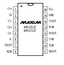 The
MAX232 requires 5 external 1uF capacitors. These
are used by the internal charge pump to create
+10 volts and -10 volts.
The
MAX232 requires 5 external 1uF capacitors. These
are used by the internal charge pump to create
+10 volts and -10 volts.