|
A Preamp Cable is a phantom powered
discrete FET (Field Effect Transistor) preamp built into
the plug of a guitar cable. It provides almost all the
advantages of an on-board preamp with none of the
disadvantages.
To the best of my knowledge I invented
the Preamp Cable in 1992 and improved it in 1996, though
it wouldn't surpise me if someone has done this before.
I've built up a number of prototypes with subtle
variations and have been using them ever since.
This article is a report about several
interesting aspects of the project. It is not a set of
step-by-step instructions for constructing a Preamp
Cable, although it's close.
While the voltage off an electromagnetic
guitar pickup can be a healthy 2.0 Volts or so
peak-to-peak if you're playing hard, the impedance of
that signal varies greatly over the frequency spectrum
and a high impedance signal can be damaged interfacing
to the outside world. The load capacitance of a guitar
cord can attenuate the high frequencies and lower the
tuning of the resonant peak of the pickup. The input
impedance of a guitar amp, mixer or effects boxes can
attenuate or distort parts of the guitar signal. And
because the guitar signal is not very robust, external
noise sources and grounding can become serious problems.
The guitar's volume control further increases the output
impedance, multiplying the problems.
Piezoelectric pickups suffer similiar
problems, though the exact mechanisms are different.
A preamp can address these problems by
acting as a buffer, providing the guitar pickup with an
optimal high impedance load and driving the cable,
effects boxes, and amplifier with a robust signal. The
sound is ballsier, brighter, and more responsive.
"It preamps anything it touches."
You can get most of the advantages of
having a preamp installed in your electric guitars,
basses, or piezo-equipped acoustic instruments
-
without having to carve up the your
favorite instrument (which can be important if it's an
especially valuable vintage model)
-
without having to install a bypass
switch in case the preamp or battery fails
-
without having to wear out the limited
number of screw/unscrew cycles of the instrument's wood
every time you replace the battery
-
without having to build a seperate
preamp into each of your instruments.
Additionally, it's easy to carry extra
Preamp Cables as backups in case of failures.
(An interesting question comes up; are
there circumstances where an on-board preamp has an
advantage over the Preamp Cable? Sure; exotic pickup
mixing or cases where you want to preamp the pickups
individually before mixing them.)
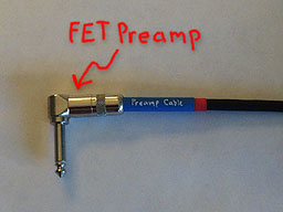
The preamp itself is a high quality, low
noise discrete FET circuit described in my article A
Discrete FET Guitar Preamp. The design allows the
circuit to be split into two parts at the point where
the FET is powered. The FET and a few associated parts
can be built into a standard 1/4-inch phone plug on the
near end of the cable while the remainder of the
circuitry and the battery can be housed in a small MXR-sized
box on the far end of the cable.
The preamp has a very high input
impedance (3.0 M ohm), a reasonably low output impedance
(6.0K ohm), and a slight voltage gain (around 3dB). It
does not use opamps and therefore avoids several classes
of distortions that I personally don't like.
The Preamp Cable is "phantom powered",
meaning that the power to drive the preamp circuitry
shares the same wire (the same piece of copper) as the
audio signal. This removes the weight and the bulk of a
battery and allows the preamp to be built into a
standard phone plug.
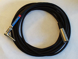
An XLR connector is used on the far end
because it has a more reliable connection for the dc
current that will be present, so the Preamp Cable will
not be confused with a regular guitar cable, and so the
Preamp Cable can be connected to a standard phantom
powered mic input.
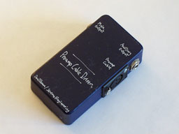
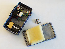
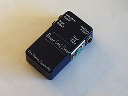
The little midnight blue box contains a
9-volt battery to power the preamp as well as circuitry
to split out the audio from the power. No power switch
is necessary as plugging the Preamp Cable into the box
effectively turns on the power. There is a second
convenience "Auxiliary Output" jack for a tuner.
Battery life us six months or
thereabouts, depending on use of course. (Long battery
life is hard to measure.)
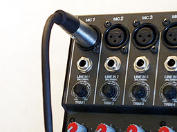
As an extra feature, it turns out that
the Preamp Cable can just as well be used with standard
phantom powered microphone inputs on a mixer (48 Volt,
6.8 Kohm, balanced). This is the way I typically use it.
Also, you can use a standard microphone
cable to extend the length of a preamp cable.
Here is the schematic and parts list for
the Preamp Cable:
Preamp Cable parts list
-
Q1 J201 N-channel JFET
-
R1 3.0 Mohm 1/8-watt 5% resistor
-
R2 20 Kohm 1/8-watt 5% resistor
-
R3 2.2K ohm 1/8-watt 5% resistor
-
P1 1/4-inch phone plug, Switchcraft 280
(straight) or 226 (right angle)
-
P2 3-pin XLR plug, Switchcraft A3M or
Neutrik equivalent
-
1/8 watt resistors are necessary for the
circuit to fit in the space inside the 1/4 inch phone
plug.
The circuit is simliar to the left half
of the circuit in my Discrete FET Preamp article. A 20
Kohm resistor has been added to the input for protection
from static discharge as the plug will spend some time
waving around in the breeze.
Obviously this is not the place for a
cheap plug. I've used both the Switchcraft 280 straight
1/4-inch plug and the Switchcraft 226 1/4-inch right
angle plug. The straight plug is preferable for the
inset jack on a Fender Stratocaster while the right
angle plug is preferable for most other instruments.
Alternately a Neutrik plug can be used; the Neutrik
plugs actually have a little more available space.
(Later note: I will definitely be using
the larger Neutrik 1/4-inch plugs for future preamp
cables. My eyes aren't what they used to be and the
Neutrik models seem to have more working room. Also
their large size suggests that this is not just a
regular guitar cord.)
Due to FET manufacturing consistancy
issues and power supply limitations, the FET needs to be
hand selected for the best performance from this
circuit. I recommend building up a breadboard version of
the circuit and substituting FETs until the voltage at
the drain is closest to 6.0 volts.
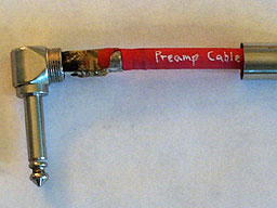
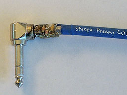
The circuitry is crammed into the space
inside the plug. This is not an easy operation and a
small-tipped low power soldering iron is essential. As
is a lot of patience.
By itself the circuitry would be
susceptable to mechanical strain from regular cord use,
so the inside volume of the plug is filled with epoxy.
Black electrical tape works well to hold the epoxy in
place while it hardens as well as insulating any solder
connections from the plug case. Additionally, heat
shrinkable tubing helps to limit the mechanical abuse of
the cable at the stress point. And labeling the cable is
important.
The XLR connector wiring is somewhat
compatible with the AES XLR spec:
XLR Connections
-
XLR pin 1: Ground
-
XLR pin 2: Signal output
-
XLR pin 3: Ground
Preamp Cable Phantom Power Box
construction
Here is the schematic and parts list for
the Phantom Power box:

-
R1 6.8 K ohm 1/4-watt 5% resistor
-
R2 51 K ohm 1/4-watt 5% resistor
-
C1 4.7 uF electrolytic capacitor
-
J1 Switchcraft D3F XLR jack
-
J2, J3 Switchcraft "11" 1/4-inch phone
jacks
The enclosure is an off-the-shelf
Hammond Manufacturing 1590-B die-cast aluminum box, 2.34
x 4.39 x 1.22 inch (60 x 112 x 31mm). Guitarists call it
an "MXR box".
"Anything worth doing is worth
overdoing."
Not only is it possible to pack a preamp
into a phone plug, it is also possible to pack two
preamps in a phone plug.
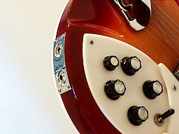
I'm a big fan of Rickenbacker guitars,
and many Rickenbacker models come with stereo wiring. On
these models there are two separate output jacks; one
labeled mono and one labeled stereo. Typically one uses
the mono output, but the stereo output has the bridge
pickup through the bridge volume and tone contols on the
tip terminal and the neck pickup through the neck volume
and tone controls on the ring terminal. Rickenbacker
calls their stereo wiring "Rick-O-Sound".
The stereo wiring can be very useful. A
stereo 12-string instrument sounds heavenly. A guitar
can have a lot of space when one pickup goes through one
effect while the other pickup goes through another. You
can fade in effects with the volume controls. Or you can
set up the neck and bridge pickups as separate presets
and use the pickup switch to bop between them without
physically being near a stompox.
A Stereo Preamp Cable takes advantage of
this.
The Stereo Preamp Cable uses a stereo (3
conductor) 1/4-inch phone plug. I've used the
Switchcraft 236 (right angle), but the Switchcraft 297
(straight) or the Neutrik equivalents should work fine.
As with the mono version, this is not the place for a
cheap plug. The Preamp Cable circuitry is doubled, once
for the tip, once for the ring contact. Construction is
obviously more difficult due to the physical size
issues. Here in the photo some of the circuitry can be
seen inside the epoxy potting.
It would be a good idea to hand-match
the FETs for the stereo Preamp Cable.
A stereo version of the Phantom Power
box doubles the circuitry of the mono Phantom Power box.
This table show the stereo wiring
assignments from guitar to final outputs:
Stereo wiring assignments
-
Guitar signal: bridge pickup neck pickup
-
Stereo phone plug: tip ring
-
XLR plug: pin 2 pin 1
-
Output jacks: "Left/Mono" "Right"
An XLR Splitter Cable is required to run
the stereo guitar directly into the phantom power mic
inputs of a mixer. The Splitter Cable has a female XLR
input plug and left and right maIe output plugs wired
this way:
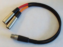
female XLR pin 1 to right male XLR pin 2
female XLR pin 2 to left male XLR pin 2
female XLR pin 3 to the remaining pins
of the male plugs as well as the cable shield
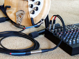
My personal favorite approach combines a
Rickenbacker 370 12-string with stereo outputs, a stereo
Preamp Cable, an XLR splitter cable, and a Mackie mixer.
This is what I used on all the 12-string guitar parts on
the Tesseract album.
Until someone goes into production with
it you have to build one yourself.
I've only built a handful of prototypes
for myself and a couple of friends. I'm not in the
Preamp Cable manufacturing business, so I'm not going to
be making any more except to try out some improvements.
In the summer of 1996 I shopped the
Preamp Cable around, showing it to various folks in the
business, asking for advice and opinions, and searching
for someone interested in manufacturing and distributing
it. I was not successful, but I probably gave up too
early. (Special thanks to John Hall of Rickenbacker,
Roger Powell of Utopia, Bill Richardson of Gryphon
Strings / StudioGuitar and the folks at Gelb Music for
all the expertise and words of advice!)
Is the Preamp Cable patentable? Phantom
powered preamps have been around for a very long time so
the basic technology is not new, and this application is
pretty much exactly what phantom power was designed for
in the first place, but this specific implementation has
some innovative details. Nonetheless, a patent must be
filed within a year of public disclosure, and since I
let the cat out of the bag years ago, a patent is not
going to happen.
I would be happy to work with a company
to make the Preamp an actual product. (Ah, the real
reason for this article.)
If I were to build another batch of
Preamp Cables I would make some improvements.
-
Use an even lower noise FET.
-
For more headroom, run the Phantom Power
box at 18 Volts instead of 9 Volts, and optimize the FET
circuit for that voltage.
-
Use an FET differential amp to reduce
hum and noise and also be more compatible with the AES
XLR spec.
-
Some other variations I'm still
considering.
|
