|
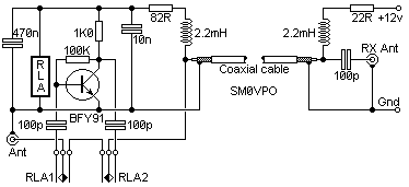
The first circuit is a simple
preamplifier showing the power arangements for conveying
DC to the amplifier via the coaxial cable. The second
circuit is a small modification so the antenna can still
be used for transmitting.
Here is a practical circuit of an RF
masthead preamplifier with DC power provided down the
coaxial feed-cable.

The actual preamplifier in this circuit
is a practical wideband amplfier that gives about 15 -
20dB of gain from 1.8 MHz through to well over 200 MHz.
You will no-doubt replace this circuit for your own
favorite amplifier for the band you are interested in.
The 2.2mH chokes should have an absolute minimum
reactance of 5000 ohms at the lowest frequency to be
used. For 145 MHz these may simply consist of a few
turns of wire. I personally used a 10-turn 4mm Dia. coil
in series with a 2.2mH torroidal inductor.
The above circuit may be modified to
allow a transmitter to be used through the masthead
preamplifier with the addition of a relay switch.

The relay should have a coil resistance
in excess of 1000 ohms and have two-pole changeover
contacts. When I built this circuit I used two 5v PCB
mounting relays, each having a single pole changeover
contact. The relays each had a 560 ohm coil.
If the DC power is switched OFF the
preamplifier will become inactive and the relay will
pypass the amplifier. In this manner it may be used with
a low-power transmitter (typically up to 10 watts). My
first switch was built inside the balun housing of a
2-metre beam antenna.
Note that the DC 12 volts should NEVER
be applied whilst transmitting or the poor little BFY91
will be blown to bits. There is also a short delay
between removing the DC and the preamp dropping out into
a safe condition for transmitting |