|
Capacitance Probe
A simple probe can be made using
insulated wire. The insulation is then the dielectric of
an annular capacitor with the inner conductor as one
plate and the water as the other. The probe is not
suitable for distilled or very pure water because it is
not conductive enough. It works well even in relatively
clean water such as roof runoff water in a plastic tank.
PVC plastic coated multistrand hookup wire will work but
is porous and may eventually give trouble. Better to use
the PTFE (teflon) equivalent. Enamelled copper wire
gives a high capacitance per unit length because the
insulation is very thin and this is suitable for short
probes of up to about 200mm. For long probes a pipe with
a sliding clamp to tension a single wire works well.
Keep the wire away from the pipe to avoid turbulence
effects. The problem with a single wire is sealing the
end under water, especially the PTFE type. It is better
to make a loop to form a U shape so that both ends are
out of the water, of course only one end needs to be
connected to the electronics, with the metal frame being
the other connection to the electronics common and to
the water. A side benefit is that the capacitance per
unit length is doubled but in the case where the probe
is being used to measure wave height it must be aligned
so that both arms of the wire are normal to the wave,
otherwise an error could result. Light springs can be
used at the top to maintain wire tension. Make sure
there are no sharp edges at the bottom of the U where
the wire is held to the frame.
The probe needs to be attached to
something fixed like the side or top of a water tank, or
to a pier. If the water depth is not too great a stake
can be driven into the bottom of a river or dam and the
probe attached to it.
The electronics should be above water in
a waterproof box that is attached to the metal probe
frame. The box cannot be separated some distance away
from the probe because the capacitance of a cable would
be too great compared to the probe capacitance. The
output cable can also bring low voltage unregulated DC
power to the unit. It can be long and even be under
water back to dry land if required.
Electronics Units
A simple analog unit can be made using a
LM324 quad op. amp.
One op. amp is configured as a 5kHz
oscillator and a fraction of the output from it is fed
to the non-inverting input of a second op amp. This is
configured as a non-inverting stage with the probe
connected to the inverting input and ground and a
"range" capacitor connected from the output back to the
inverting input. The output level from this stage starts
at the same as the input level and goes up with wave
height or depth. Two 10M ohm resistors in series are
placed across the range capacitor to reduce 50Hz/60Hz
pickup.
The output is high pass filtered and
rectified to DC. The third op. amp is a differential
stage that subtracts the rectified DC from the output
from a potentiometer connected to +5V for zero
adjustment. The output from this stage is low pass
filtered to 20Hz and the final op. amp is a
non-inverting stage with amplification.
Total current from a 9V battery using
+5V and -5V micropower regulators together with a
ICL7662 charge pump inverter is about 1.8mA.
Output is in the range of +/- 3.5 volts.
The capacitance probe is connected to an
ICM7555 running in astable mode. The 7555 has the
advantage as an oscillator for this application because
the capacitor is grounded. The resistor values are
chosen so that the minimum frequency is above 5kHz. The
minimum occurs at the maximum water level.
The probe and it's connections have some
capacitance out of water and will determine the maximum
frequency. The ICM7555 has a maximum frequency of about
500kHz.
The period of oscillation is
proportional to the capacitance and therefore to the
water level. The period is measured using the
timer/counters of a microcontroller, the Microchip PIC
16F876. The output of the ICM7555 is connected to pin
RA4 which is timer 0 clock input via a prescaler.
Timer 0 byte is preloaded with a value
and an interrupt is generated when it overflows. A fixed
number of 7555 pulses are therefore counted.
There is some jitter in the 7555
frequency so it is necessary to count a large number of
pulses to get the average period. One thousand is
sufficient, but it is a tradeoff. For tank water level
measurement the time taken can be long but for wave
measurement it is necessary to have a higher overall
sample rate.
The time taken for timer 0 to overflow
is measured by the 16 bit timer 1 counting the crystal
frequency divided by four. The crystal is 4MHz so the
value in timer 1 is in microseconds. Any overflows of
timer 1 are counted by counting the overflow interrupts.
The two resistors needed on the 7555 are
both 21k ohm and are low temperature coefficient types
from the RC55 series from Farnell or equivalent. They
have coefficients of 15 parts per million per degree C.
The Philips ICM7555 itself has a temperature coefficient
of around +0.02% per degree C. This means that for a
depth of 2000 mm and a 50 deg C. temperature change on
the 7555, the output will change by 20 mm. Depending on
the application, this may be a significant error.
In the present unit the ambient
temperature near the 7555 is measured using a digital
temperature sensor, the Dallas DS1624, and the measured
temperature is used to immediately correct the 7555
period measurement to that at a reference temperature of
0 deg C. The correction can be set for a particular 7555
for best results because there is some variation in the
temperature coefficients.
The timer 1 count is scaled to
millimetres and output to the RS232 serial port in ASCII
format so that the data can be viewed and saved to a
file using a terminal program such as Hyperterminal in
Win 95/98. Temperature is also output with a resolution
of 0.1 deg C. and accuracy of 0.5 deg. C.
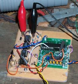
A photo of the prototype board hooked up
to a rainwater tank.
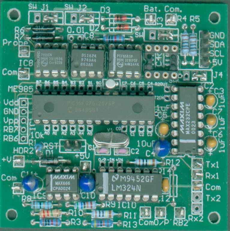
A photo of the complete board.
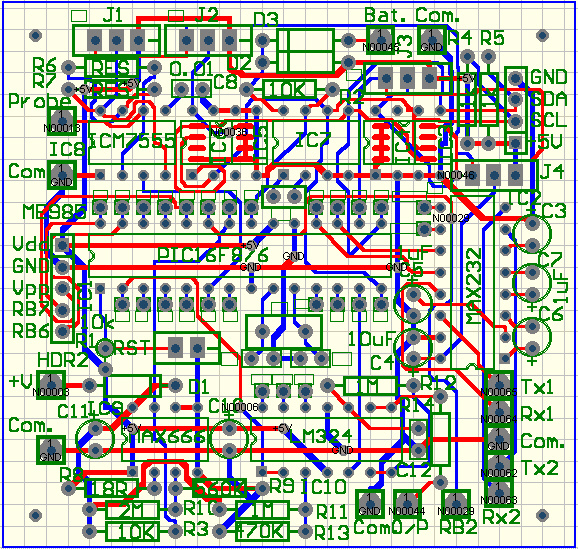
Layout of PCB.
There are Protel files for a printed
circuit board for this unit. The board is
67mm by 64mm.
In addition to the 7555, 16F876, and
DS1624 chips mentioned earlier the board has provision
for components that may be omitted for some applications
that dont need them.
Where a component is available with
dual-in-line pins as well as in surface mount both
footprints are provided, one within the other.
The Philips PCF8583 IIC bus
clock/calendar chip can be used to date/time stamp the
level and temperature data. Also, the alarm output is
connected to the external interrupt pin (RB0) of
the16F876. This can be used to wake the microcontroller
from a low power sleep state after an interval of 1 to
100 seconds or 1 to 100 minutes. When the external
interrupt occurs, the handling routine clears the timer
flag on the PCF8583 and also reloads the PCF8583 timer
register with (100 - interval needed).
The Microchip 24LC256 IIC bus 256K bit
serial EEPROM can be used to store data for later
retrieval. More of these devices with different
addresses up to a total of eight can be added by
connecting them externally. Other IIC bus devices such
as an lcd display can be added by connecting them to the
IIC bus connector.
There are jumpers to either connect a
device permanently to +5V or to have it powered by bit
RC5 only when required. For example, the MAX232 consumes
about 10mA, but can be powered only when data is to be
sent out.
The MAX666 micropower +5V regulator has
a /LOBAT output that is connected to pin RB1 to flag a
flat battery. In addition the battery voltage can be
monitored and output in the data if needed.
A high value resistive divider is
buffered by an op. amp. that is connected to pin RA0,
A/D input 0. The op. amp. is needed because to maintain
10 bit accuracy there a 10k ohm inpedance limit on the
A/D input and low value resistors would consume too much
power. If the LM324 op. amp. is omitted a compromise is
possible using 100k ohm and 47k ohm resistors because
only low precision measurement to 0.1V is needed.
The measurement is only valid down to 7V
because below that the MAX666 regulator drops out, and
the A/D reference is +5V. Below 7V the /LOBAT signal
should be used to flag invalid data. The program adds
0.7V to compensate for the reverse voltage protection
diode D1.
PWM can be output if needed, to control
a pump motor for example. An analog output can be
derived by filtering the PWM1 output with R12 and C12.
RB2 is brought out to a pin as a control
bit. For example it can be used to turn on a pump to add
water to a tank when the level falls below a level set
in software. Variables like this and the probe
calibration constant can be stored in the EEPROM area of
the 16F876.
|
