|
I have to say from the outset that I do
not agree with the use of weighting filters, since they
are not (despite the claims to the contrary) an accurate
representation of human hearing.
In fact, the standard "A" weighting
curve is accurate at only one SPL (Sound Pressure
Level), assuming that the listener has British Standard
Ears. I have no idea what SPL this filter is meant to be
accurate at, and I doubt that anyone else does either
(although at a rough guess I would suggest somewhere
around 50dB and below).
When the police measure the noise from a
car exhaust or a party, they happily use A-weighting
(it's probably in the legislation - that has to be scary
- politicians thinking that they know about SPL? Next
thing they will tell us that they understand fiscal
policy. But I digress .....
The purpose is supposedly to account for
the fact that human hearing is less sensitive at low and
high frequencies than in the upper midrange, and that
this variation is dependent upon the sound intensity (SPL).
The Fletcher-Munson curve (as it is commonly known, and
reproduced below) shows the variation, and it is clear
that any loss of sensitivity is highly dependent upon
the actual SPL. The idea that a single filter can
represent this at all levels is clearly wrong, but it is
a standard nonetheless. (Interestingly, being wrong has
never stopped a standard from being imposed, and this is
probably truer in the audio industry than almost any
other I can think of.)
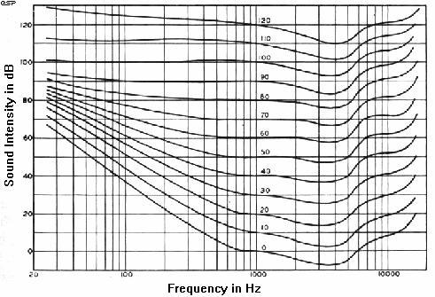
Figure 1 -
Equal Loudness Curves (After Fletcher and Munson)
The premise behind all this is that as
the SPL is reduced, our ability to detect low or high
frequency noise is reduced, so measurements should
reflect this phenomenon. While it is undeniable that the
chart above represents reality in terms of human hearing
[1], I remain unconvinced that A-weighting is a valid
test methodology unless the absolute sound intensity is
specified.
Ok, I agree that there just might be
some validity hiding in there somewhere for noise
measurements of amplifiers and the like, but just
because the meter tells me that I should not be able to
hear the harmonics of the 50/60Hz mains, does not mean
that I cannot. There are some sounds that seem (at a
casual glance) to defy all measurement standards, and
remain audible (albeit at very low level) despite all
the "evidence" that this should not be so. As with all
such things, experience and practical application are
more important than the absolute indication on a meter.
A piece of equipment that is essentially
"noise-free" for all intents and purposes is in reality
a waste of time, since the ambient noise level in most
urban or suburban areas is likely to be far higher than
the residual noise of most audio equipment. How useless
is 100dB signal to noise ratio for a car hi-fi system,
for example? Even the most expensive luxury cars
generate far more noise than any tuner/cassette/CD
system (and this is apart from all the other external
noise generated by other vehicles on the road).
Since it is unlikely that I shall be
able to convince the entire industry that it is using
flawed reasoning, I shall describe an A-weighting filter
so that we can at least make some meaningful comparisons
with other systems where this has been used. Note that
A-weighting is generally applied only to noise
measurements, so might have some validity in this
respect (as long as the noise we are measuring is of
very low amplitude - the neighbour's party is unlikely
to fit this mould, but will be measured with A-weighting
anyway - oh dear - so much for getting some sleep! (And
yet again I digress .... ))
The curve of the described filter is
shown in Figure 2, and it can be seen that it is
essentially a tailored bandpass filter, having a defined
rolloff above and below the centre frequency. The
reference point is at 1kHz, where the gain is 0dB. The
filter response is supposed to be the inverse of one of
the curves of the equal loudness graph shown in Figure 1
- it is a little hard to tell which one, but this is a
standard, so we shall leave it at that.
As can be seen from Figure 3, the
circuit is very simple, but even with this frequency
response it is not particularly hard to calibrate
accurately so that it really does account for our
perception of noise level - especially if an accurate
sinewave tone is used as the reference.
Figure 2 - Frequency Response of the
A-Weighting Filter
The filter itself is passive, and the
opamps are there only to buffer the input and output,
and to adjust the gain so there is some correlation with
reality (however slight). Note that the input impedance
is quite low, and the output impedance is high, so the
unit should be well shielded to prevent noise pickup
from the outside world.
As always, I suggest the use of 1% metal
film resistors, and the capacitors should be measured
and selected, or close tolerance types used. If
"ordinary" capacitors are used, their tolerance will
adversely affect the accuracy, but for normal use (i.e.
non-certified laboratory), it should be close enough
even if 10% caps are used. After all, the noise level of
any semiconductor amp is likely to be somewhat variable
anyway, so extreme precision is not normally warranted.
The circuit can be operated from a pair
of 9 Volt batteries, or a regulated supply of up to
+/-15V. There is no need to use premium opamps unless
extremely low noise levels are to be measured, and even
then are not needed if there is a gain stage at the
front end.
Figure 3 - The A-Weighting Filter
Schematic
I will leave it up to the reader to
decide on the opamps - I suggest a TL072 dual FET device
or similar, which should be ok for most applications
(they are not too bad for general purpose work). No
opamp pinouts have been included, these are available on
any manufacturers' data sheet if you don't know them.
Basic calibration is not hard - the
overall gain at 2,700Hz is supposed to be about 1.3dB,
so if the input is set to 1V RMS, the output at 2.7kHz
should be 1.162V. Alternatively, at 1kHz, the gain (or
insertion loss) should be 0dB - I would suggest that it
is checked at both frequencies if possible, and if
necessary, average the error between the two
frequencies.
Use the 10k trimpot to adjust the level
(you need to be accurate with your measurements if true
A-weighting is to be obtained). Note that the trimpot
should be a quality multi-turn "Cermet" (Ceramic-Metal
Film) type to enable accurate setting and long-term
stability. Alternatively the trimpot may be replaced
with a 5.6k resistor, and accuracy will be quite
acceptable for most applications (the error is less than
0.2dB).
So, there you have it. This project will
enable you to make "industry standard" measurements of
amplifier noise levels, it is up to you to decide which
particular standard you want to make comparisons
against. Life would be so much easier if all noise
measurements were made "flat" - with no filters of any
kind, but this is not to be.
|
