-
Power input: 230V AC 50 Hz 10A max.
-
Number of output channels: 4
-
Output power: 900W maximum per channel,
2300W maximum total
-
Fusing: 4A fuse per channel, 10A breaker
on mains input
-
Controlling: standard 0-10V input
-
Case: Plastic case
Remotely controlled light dimmers in
theatrical and architechtural applications use 0-10V
control signal for controlling the lamp brightness. In
this case 0V means that the lamp is on and 10V signal
means that the lamp in fully on. A voltage between those
values adjust the average voltage which is applied to
the ligh bulb. This average voltage controlling is made
by controllign the position in which phese the output
triac fires (sooner it fires more power is applied to
lamp).
The the phase when the TRIAC will fire
is controlled by the input voltage which is compared to
an internal ramp signal generated by the dimmer. In this
arrangement the input voltage linearly controls the time
delay between mains zero crossing and the triac
triggering.
Circuit diagram
This circuit is a real core of the
dimmer system. This circuit generates ramp 100 Hz signal
which is syncronized to the incoming mains voltage. The
ramp signal which is generated will start form 10V and
go linearly down to 0V in 10 milliseconds. At the next
mains voltage zero crossing the ramp signal will again
immediatly start from 10V and go down to 0V. This same
ramp signal is fed to all of the 4 comparators in the
dimmer.
The following ramp signal generator is
quite simple ramp generator based on discrete
transistors which do some switching, capacitor and a
constant current source made by using one transistor.
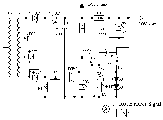
Trimmer R5 is used in controlling the
ramp signal. If you have an oscilloscope, then it is
best to use it to look at the situation so that the
signal send by the circuit is what is described eariler.
A good approximation is so start at position that R5 is
set to it's center position.
Besides generating the ramp signal the
sampl generator circuit works as a power supply
comaprator part of the dimmer. The 13.5V unstabilized
output is used to power the comparator section (that
putput can be loaded up to 100 mA). The 10V stabilized
voltage is used only for internal use in ramp generator
(that stabilized 10V voltage can be also used for some
extra low power circuitry which need 10V voltage, for
example local dimmer controls if such thign are needed).
The ramp generator used a normal mains
transformer which can output at least 200 mA of current,
because it powers both ramp generator itself and the
voltage comparator circuits. I relected a tranformer
which has an invernal overload protection inside the
transformer (overhating protection fuse), so I did not
need to add any extra fuses for this transformer. If you
use other kind of transformer, select a suitable fuse to
protect it. In any case a 200 mA fuse on the secondary
would be a good idea, propably also a primary fuse.
R1 10 kohm 0.25W
R2 1 kohm 0.25W
R3 1 kohm 0.25W
R4 100 ohm 1W
R5 470 ohm trimmer
R6 10 kohm 0.25W
C1 2200 uF 25V electrolytic
C2 1000 uF 25V electrolytic
C3 2.2 uF 25V
D1-D5 1N4007
D6-D7 10V zener diode 1W
D8-D9 1N4148
Q1-Q3 BC547
TRANS Transformer 230V primary and 12V 200 mA secondary
|
