|
An analogue signal is similar to a sine
wave and is generally less than 5v (5,000mV) in
amplitude. Low-level signals are generally expressed in
mV, to make them instantly recognisable and easy to talk
about.

Fig: 1shows an analogue signal. It may
be as low as a few millivolts or hundreds of millivolts.
In general this type of signal will be too small to be
detected by a microcontroller. A micro needs a signal
greater than about 3,500mV so that the waveform appears
on the input line as a HIGH, during the peak of its
excursion. It should be as high as 5,000mV as possible
for reliable detection of the signal. The instruction to
"read" the HIGH is:
BTFSS 06,3 ;
Test input line GP3
This instruction tests line GP3 and if
the bit is HIGH (the line is SET - the line sees a HIGH)
the micro will skip the next line in the program and
execute the line that follows in the program.
The shape of the waveform does not
matter. It can consist of large excursions and small
excursions as shown in fig: 2.

Only the large excursion(s) will be
detected by the micro as the others may be too small to
be detected. To increase the analogue signal to as high
as 5,000mV as possible, an amplifier is needed, as shown
in fig: 3.
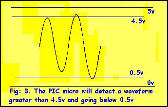
The amplifier maybe one or two stages,
depending on the amplitude of the original signal.
Each stage of an amplifier will increase
the size of the signal about 70 times. If you are very
lucky, you may get an amplification of 100x (100 times).
Thus a 5mV signal with one stage of amplification will
produce a 350mV signal. This is not sufficient to be
detected by the micro. Another stage will easily produce
a full 5,000mV signal and the micro will detect its
presence.
The second stage only needs to amplify
the signal about 10 to 12 times to be sufficient for the
micro, and the added gain provided by the stage simply
drives the waveform into "bottoming" and "cut-off" as
shown in fig: 4.
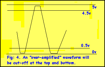
This means the waveform will be
"clipped" at the top and bottom and converted to a
fairly "square-ish" shape. Normally this would be called
distortion but in digital terms we don't worry about it
being distorted and simply use it for its "triggering"
properties.
Suppose you have a waveform that is
higher than 5mV (say 30 - 50mV) and want to know if it
will trigger the micro after a single stage of
amplification.
Connect the circuit in Fig: 5 to the
micro and connect a LED with 470R resistor in series, to
pin GP0.
Burn the following routine into a
PSEUDO'508 and the LED will illuminate when the waveform
is detected as a HIGH.
Program for a Pseudo'508:
BSF 03,5 ;Select Page1
MOVLW 08 ;GP3 input
TRIS 06 ;Load TRIS
BCF 03,5 ;Select Pag0
Test1 BTFSS 06,3 ;Test input line
GOTO Test2
BSF 06,0
GOTO Test1
Test2 BCF 06.0
GOTO Test1
There is only one problem with the
circuit in Fig: 5.
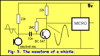
At the end of a whistle or speech, the
LED may be illuminated or extinguished. It all depends
on the last cycle of the waveform. The circuit sits with
the output approx mid-rail and the micro does not know
if this is a high or low, and takes the reading by the
direction of the last cycle.
Some of the inputs of the micro are
Schmitt Triggered. This means a HIGH has to be 85% to
100% of rail voltage for it to be seen as a HIGH and
between 20% and 0% to be seen as a LOW.
The non-Schmitt Trigger inputs see a LOW
as 20% to 0% and a HIGH as above 2v for 5.5v operation.
If the last cycle went from zero to
mid-rail the micro will see the waveform as a low on
Schmitt Trigger inputs and a HIGH on the other inputs.
If the cycle came from a high to about mid-rail, the
waveform
will be seen as a high. This problem can be overcome via
a few instructions in the program, by looking at the
input and if it is not changing, it is ignored. Suppose
the circuit only just activates the micro with a loud
whistle. To improve the sensitivity of the input another
stage will be needed.
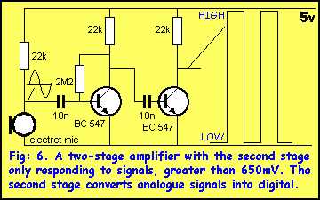
This can be a DIGITAL STAGE as shown in
fig: 6 or an analogue stage as shown in fig: 7.
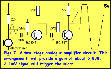
A digital stage simply means the biasing
resistor is left off the base of the second transistor
so the transistor turns on fully when a signal greater
than 650mV is detected and is fully turned off at other
times. This stage is ideal for the micro as only two
voltage levels are delivered. Either 0v or rail voltage
(5v).The other advantage is the stage does not take any
quiescent (idle) current.
This stage is only suitable if you are
sure you have plenty of "over-voltage" to drive the
transistor into saturation. By this we mean you must
have at least 1v (1,000mV) drive signal so you can be
sure the transistor will turn on (saturate).
The fast rise and fall times means you
have a "clean" period of time during a HIGH or LOW for
counting operations. A micro determines the frequency of
an incoming signal by counting the length of time for
the HIGH or LOW (between a rise and fall) and coming to
a decision as determined by the program. If the lengths
of the HIGHs and LOWs are very regular the micro can
come to an accurate decision very quickly. This is very
important if you are detecting a particular frequency
out of a possibly range of frequencies as the program
will compare the incoming frequency with a table value
and it may keep sampling until an exact match is
produced.
Fig 7. Shows two analogue stages with
"over-drive." The circuit produces a signal that is
larger than necessary for the micro, and when the input
waveform is very low, the output will still be
sufficient to
trigger the micro.
This circuit is more sensitive than fig:
6 and should be used if you want to pick up faint
whispers and turn on equipment (such as a tape
recorder). It should also be used for magnetic pick-ups
(such as a
metal detector, nail finder or pipe locator) as this
type of pick up has a very low output (can be as low as
1 to 5mv).
THE PIEZO DIAPHRAGM
Piezo transducers such as piezo
diaphragms can also be used as microphones. They produce
a very "tinny" sound (like talking into a tin) but this
is not important in our case. The output is about the
same as an electret microphone (about 10 to 30mV for low
level speech and up to 50mV for loud speech).
Some diaphragms are very sensitive while
others are very insensitive. You can check the
sensitivity with a CRO, by simply whistling and viewing
the waveform.
Diaphragms that operate on low voltages,
such as those in a music card seem to very sensitive.
The only other way to determine a
sensitive piezo diaphragm is to connect it to a music
chip. The output it produces reflects its sensitivity as
a microphone.
The piezo diaphragm has an advantage
over an electret microphone. It does not need a power
source.
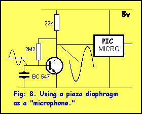
The diagram of fig: 8 shows how to
connect it to a transistor amplifier. Using the program
above, whistle into the diaphragm and determine if a
single stage is sufficient. If not, a second stage,
exactly like the microphone stage can be added.
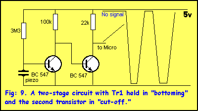
Fig 9 shows a simpler circuit to
interface a piezo diaphragm to the input of a micro. The
first transistor is held in "bottoming" and the second
in "cut-off." This offers the lowest current consumption
and produces the greatest output. The second transistor
is "turned-off" because the first transistor is "ON" and
the voltage across its collector-emitter terminals is
about 0.35v and this is below the turn-on voltage of
0.65v for the base of the second transistor. The first
transistor is fully turned on but the turn-on current is
very low and this allows the maximum waveform to be
produced by the piezo for a given sound intensity. In
other words the circuit puts the lightest load on the
piezo.
When no-signal is present, the output of
the circuit is HIGH.
A signal from the piezo produces a
full-rail waveform to exactly match the waveform from
the piezo.
By monitoring the output of the circuit
you will be able to detect the instant the waveform
produces a LOW. Instructions that loops until a low is
detected are shown below:
Loop1 NOP
BTFSC 06,0 ;Test GP0 for a LOW
GOTO Loop1
The only problem with loop1 is it holds
up the micro from doing any other operations.
The solution is to "poll" the input line
by producing a program that "looks" at the input on a
regular basis and if a low is detected, a "bit" is
placed in a flag register. The Main routine constantly
looks at the flag register and when the bit is SET, it
carries out an operation and cancels the flag.
MAGNETIC PICKUP
A 10mH choke (with both wires coming out
the same end so the magnet can pass as close as possible
to the core) can be used as a magnetic pick-up to detect
rotating shafts etc. The circuit in fig: 10 will connect
it to a micro.
Attach a strong magnet to a rotating
shaft and have the magnetic sensor close to the magnet
as possible without touching. The amplitude of the
waveform produced by the coil (choke) will depend on the
strength of the magnet, the distance between the magnet
and coil, the speed of the rotating shaft and the number
of turns on the coil.
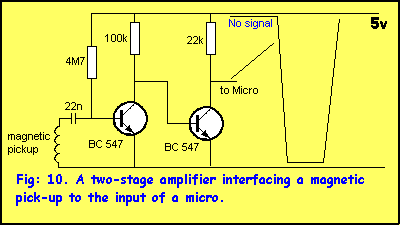
Fig: 10 "AC" couples the coil to the
amplifying circuit so that the biasing of the first
transistor can be determined by the value of the
base-bias resistor. The coil cannot be connected
directly to the transistor as the low impedance
(resistance) of the coil will upset the bias on the
base.
If the coil is directly connected to the
base, the voltage across the coil will be only a few
millivolts and the coil will have to produce 600mV or
greater to turn on the transistor.
With our arrangement, 100mV or less will
turn off the transistor (a 100mV waveform will turn the
transistor ON more during the "positive half" of the
waveform and turn it off during the other half of the
waveform).
Any coil of wire of any size will be
suitable and to make it an effective collector of
magnetic flux it should have a magnetic core such as a
ferrite.
Simply rotate the shaft at half the
required RPM and if the circuit detects the magnet, the
coil is suitable. No other impedance-matching or
resistance measurements are necessary.
The output of the circuit is exactly the
same as for the piezo diaphragm except the frequency
will be considerably less.
THE LDR
The cheapest light sensor is the LDR. It
has a resistance of about 100 ohms in bright light and
more than 1M in darkness.
It can be connected to a transistor
amplifier as shown in fig: 11.

The pot alters the sensitivity of the
LDR so that the output changes at the desired light
intensity. This circuit is only suitable for large
changes in intensity. If you need to detect a very
slight change in illumination you need a very sensitive
detector.
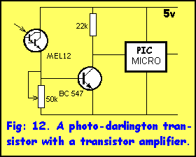
PHOTO DARLINGTON TRANSISTOR
A more sensitive device is a photo-darlington
transistor, such as the MEL-12. A further stage of
amplification and a pot will adjust the sensitivity
level. This is shown in fig: 12.
VOLTAGE LEVELS
Some waveforms change very slowly. They
may take a day or so to rise and fall. The are
classified as VOLTAGE LEVELS and can be produced by
thermocouples (a thermocouple PRODUCES a voltage due to
the heating of two different metals in contact with each
other). Other devices DELIVER a voltage by being
supplied with a voltage and the resistance of the device
causes a certain voltage to appear across it. You can
call it a VOLTAGE-DIVIDER principle. Devices that
deliver a voltage include the thermistor, diode (and
transistor) and strain gauge. This is very important as
it determines how the device is connected to either an
amplifier or the input of the micro.
THE FREQUENCY OF A SIGNAL
Once you have a waveform that triggers
the micro (use the test program given at the beginning
of this article to make sure it is being detected by the
micro) you can get the program to simply detect its
presence or determine the frequency.
The frequency can be determined in two
ways:
1. Counting the number of HIGHs and LOWs
in one second.
2. Counting the time taken for a
HIGH-to-LOW transition - one half cycle.
Method 1 is a very slow way to obtain a
frequency in cycles per second.
A micro works so fast that it can
determine things in a fraction of a second.
Method 2 is much faster but it can be
very inaccurate as the half-cycle is multiplied-up to
get the value in Hertz. To reduce the inaccuracy you can
count 10 cycles or 100 cycles and perform a
multiplication. A higher cycle-count reduces the
inaccuracy.
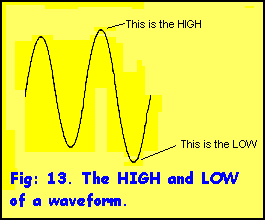
The following steps are required to
produce the value of a frequency (in Hertz). Refer to
fig: 13 for the definition of a HIGH and LOW.
The input is looped until a HIGH is
detected.
The program then goes to a short delay.
The micro comes out of the delay and
increments a "count" file.
The program looks at the input for a
LOW. If a LOW is not detected the program goes to step
B.
When a LOW is detected the program has a
value in the "count" file - this is half a cycle.
By adding-up the number of instructions
carried out during the "count" increment, the program
can work out the frequency of the waveform.
Sometimes a frequency in cycles per
second is not required. You may want to compare a
frequency with a value in a table. This is called TONE
DETECTION.
TONE DETECTION
- also called Tone decoding
The frequency of an incoming tone can be
detected and "flagged" when it is exactly the correct
tone. This is handy for detecting DTMF tones on the
phone line. In this way DTMF tones can be used for
turning on equipment (such as lighting, heating, alarms
etc). The accuracy of the tone can be set by the
program. It is best to allow a margin of error so you
can guarantee the tone will be recognised.
For best detection, the incoming tone should be "good
quality" i.e full amplitude and free from noise, so the
determination can be speedy. Fig: 13 shows a typical
waveform.
|