Microcontroller Beginner Kit -
Learning to use LEDs and Transistors
Introduction
As electronic designs
get bigger, it becomes difficult to build the
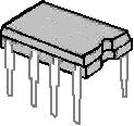
complete circuit. So we will use prebuilt
circuits that come in packages like the one
shown above. This prebuilt circuit is called an
IC. IC stands for Integrated Circuit. An IC
has many transistors inside it that are
connected together to form a circuit. Metal
pins are connected to the circuit and the
circuit is stuck into a piece of plastic or
ceramic so that the metal pins are sticking out
of the side. These pins allow you to connect
other devices to the circuit inside. We can buy
simple ICs that have several inverter circuits
like the one we built in the
LED and Transistor tutorial or we can buy
complex ICs like a Pentium Processor.
The Pulse - More
than just an on/off switch
So far the circuits
we have built have been stable, meaning that the
output voltage stays the same. If you change
the input voltage, the output voltage changes
and once it changes it will stay at the same
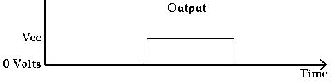
voltage level. The 555 integrated circuit (IC)
is designed so that when the input changes, the
output goes from 0 volts to Vcc (where Vcc is
the voltage of the power supply). Then the
output stays at Vcc for a certain length of time
and then it goes back to 0 volts. This is a
pulse. A graph of the output voltage is shown
below.
The Oscillator (A Clock) - More
than just a Pulse
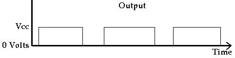
The pulse is nice but
it only happens one time. If you want something
that does something interesting forever rather
than just once, you need an oscillator. An
oscillator puts out an endless series of
pulses. The output constantly goes from 0 volts
to Vcc and back to 0 volts again. Almost all
digital circuits have some type of oscillator.
This stream of output pulses is often called a
clock. You can count the number of pulses to
tell how much time has gone by. We will see how
the 555 timer can be used to generate this
clock. A graph of a clock signal is shown
below.
.
The Capacitor
If you already understand capacitors you
can skip this part.
The picture above on the left shows two
typical capacitors. Capacitors usually have two
legs. One leg is the positive leg and the other
is the negative leg. The positive leg is the
one that is longer. The picture on the right is
the symbol used for capacitors in circuit
drawings (schematics). When you put one in a
circuit, you must make sure the positive leg and
the negative leg go in the right place.
Capacitors do not always have a positive leg and
a negative leg. The smallest capacitors in this
kit do not. It does not matter which way you
put them in a circuit.
A capacitor is similar to a rechargable
battery in the way it works. The difference is
that a capacitor can only hold a small fraction
of the energy that a battery can. (Except for
really big capacitors like the ones found in old
TVs. These can hold a lot of charge. Even if a
TV has been disconnected from the wall for a
long time, these capacitors can still make lots
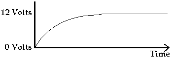
of sparks and hurt people.) As with a
rechargable battery, it takes a while for the
capacitor to charge. So if we have a 12 volt
supply and start charging the capacitor, it will
start with 0 volts and go from 0 volts to 12
volts. Below is a graph of the voltage in the
capacitor while it is charging.
.
.
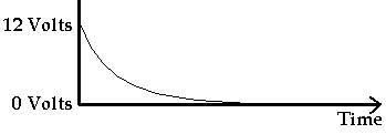
The
same idea is true when the capacitor is
discharging. If the capacitor has been charged
to 12 volts and then we connect both legs to
ground, the capacitor will start discharging but
it will take some time for the voltage to go to
0 volts. Below is a graph of what the voltage
is in the capacitor while it is discharging.
.
We can control the speed of the
capacitor's charging and discharging using
resistors.
Capacitors are given values based on how
much electricity they can store. Larger
capacitors can store more energy and take more
time to charge and discharge. The values are
given in Farads but a Farad is a really large
unit of measure for common capacitors. Common
capacitors use measurements of pf and uf. Pf
means picofarad and uf means microfarad. A
picofarad is 0.000000000001 Farads. So a 33pf
capacitor has a value of 33 picofarads or
0.000000000033 Farads. A microfarad is 0.000001
Farads. So a 10uf capacitor is 0.00001 Farads
and a 220uF capacitor is 0.000220 Farads. If
you do any calculations with formulas using the
value of the capacitor you have to use the Farad
value rather than the picofarad or microfarad
value.
Capacitors are also rated by the maximum
voltage they can take. This value is always
written on the larger can shaped capacitors.
For example, the 220uF capacitor in this kit has
a maximum voltage rating of 25 volts. If you
apply more than 25 volts to them they will die.
The 555 Timer
Creating a Pulse
The 555 is made out of simple
transistors that are about the same as on / off
switches. They do not have any sense of time.
When you apply a voltage they turn on and when
you take away the voltage they turn off. So by
itself, the 555 can not create a pulse. The way
the pulse is created is by using some components
in a circuit attached to the 555 (see the
circuit on the next page). This circuit is made
of a capacitor and a resistor. We can flip a
switch and start charging the capacitor. The
resistor is used to control how fast the
capacitor charges. The bigger the resistance,
the longer it takes to charge the capacitor.
The voltage in the capacitor can then be used as
an input to another switch. Since the voltage
starts at 0, nothing happens to the second
switch. But eventually the capacitor will
charge up to some point where the second switch
comes on.
The way the 555 timer works is that
when you flip the first switch, the Output pin
goes to Vcc (the positive power supply voltage)
and starts charging the capacitor. When the
capacitor voltage gets to 2/3 Vcc (that is Vcc *
2/3) the second switch turns on which makes the
output go to 0 volts.
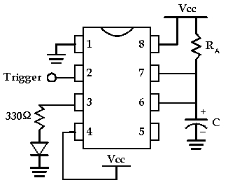
The pinout for the 555 timer is
shown below
Deep Details
Pin 2 (Trigger) is
the 'on' switch for the pulse. The line over
the word Trigger tells us that the voltage
levels are the opposite of what you would
normally expect. To turn the switch on you
apply 0 volts to pin 2. The technical term for
this opposite behavior is 'Active Low'. It is
common to see this 'Active Low' behavior for IC
inputs because of the inverting nature of
transistor circuits like we saw in the LED and
Transistor Tutorial.
Pin 6 is the off
switch for the pulse. We connect the positive
side of the capacitor to this pin and the
negative side of the capacitor to ground. When
Pin 2 (Trigger) is at Vcc, the 555 holds Pin 7
at 0 volts (Note the inverted voltage). When
Pin 2 goes to 0 volts, the 555 stops holding Pin
7 at 0 volts. Then the capacitor starts
charging. The capacitor is charged through a
resistor connected to Vcc. The current starts
flowing into the capacitor, and the voltage in
the capacitor starts to increase.
Pin 3 is the
output (where the actual pulse comes out). The
voltage on this pin starts at 0 volts. When 0
volts is applied to the trigger (Pin 2), the 555
puts out Vcc on Pin 3 and holds it at Vcc until
Pin 6 reaches 2/3 of Vcc (that is Vcc * 2/3).
Then the 555 pulls the voltage at Pin 3 to
ground and you have created a pulse. (Again
notice the inverting action.) The voltage on
Pin 7 is also pulled to ground, connecting the
capacitor to ground and discharging it.
Seeing the pulse
To see the pulse we will use an LED
connected to the 555 output, Pin 3. When the
output is 0 volts the LED will be off. When the
output is Vcc the LED will be on.
Building the Circuit
Place the 555 across the middle line of the
breadboard so that 4 pins are on one side and 4
pins are on the other side. (You may need to
bend the pins in a little so they will go in the
holes.) Leave the power disconnected until you
finish building the circuit. The diagram above
shows how the pins on the 555 are numbered. You
can find pin 1 by looking for the half circle in
the end of the chip. Sometimes instead of a
half circle, there will be a dot or shallow hole
by pin 1.
Before you start building the circuit,
use jumper wires to connect the red and blue
power rows to the red and blue power rows on the
other side of the board. Then you will be able
to easily reach Vcc and Ground lines from both
sides of the board. (If the wires are too
short, use two wires joined together in a row of
holes for the positive power (Vcc) and two wires
joined together in a different row of holes for
the ground.)
Connect Pin 1 to ground.
Connect Pin 8 to Vcc.
Connect Pin 4 to Vcc.
Connect the positive leg of the LED to a
330 ohm resistor and connect the negative end of
the LED to ground. Connect the other leg of the
330 ohm resistor to the output, Pin 3.
Connect Pin 7 to Vcc with a 10k resistor
(RA = 10K).
Connect Pin 7 to Pin 6 with a jumper wire.
Connect Pin 6 to the positive leg of the
220uF Capacitor (C = 220uF). (You will need to
bend the positive (long leg) up and out some so
that the negative leg can go in the breadboard.
Connect the negative leg of the capacitor
to ground.
Connect a wire to Pin 2 to use as the
trigger. Start with Pin 2 connected to Vcc.
Now connect the power. The LED will
come on and stay on for about 2 seconds. Remove
the wire connected to Pin 2 from Vcc. You
should be able to trigger the 555 again by
touching the wire connected to pin 2 with your
finger or by connecting it to ground and
removing it. (It should be about a 2 second
pulse.)
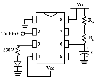
Making it
Oscillate
Next we will make the LED flash continually
without having to trigger it. We will hook up
the 555 so that it triggers itself. The way
this works is that we add in a resistor between
the capacitor and the discharge pin, Pin 7.
Now, the capacitor will charge up (through RA
and RB) and when it reaches 2/3 Vcc, Pin 3 and
Pin 7 will go to ground. But the capacitor can
not discharge immediately because of RB. It
takes some time for the charge to drain through
RB. The more resistance RB has, the longer it
takes to discharge. The time it takes to
discharge the capacitor will be the time the LED
is off.
To trigger the 555 again, we connect Pin
6 to the trigger (Pin 2). As the capacitor is
discharging, the voltage in the capacitor gets
lower and lower. When it gets down to 1/3 Vcc
this triggers Pin 2 causing Pin 3 to go to Vcc
and the LED to come on. The 555 disconnects Pin
7 from ground, and the capacitor starts to
charge up again through RA and RB.
To build this
circuit from the previous circuit, do the
following.
Disconnect the
power.
Take out the jumper
wire between Pin 6 and Pin 7 and replace it with
a 2.2k resistor (RB = 2.2K).
Use the jumper wire
at pin 2 to connect Pin 2 to Pin 6.
Now reconnect the
power and the LED should flash forever (as long
as you pay your electricity bill).
Experiment with
different resistor values of RA and RB to see
how it changes the length of time that the LED
flashes. (You are changing the amount of time
that it takes for the Capacitor to charge and
discharge.)
Formulas
These are the
formulas we use for the 555 to control the
length of the pulses.
t1 = charge time
(how long the LED is on) = 0.693 * (RA + RB) * C
t2 = discharge time
(how long the LED is off) = 0.693 * RB * C
T = period = t1 + t2
= 0.693 * (RA + 2*RB) * C
Frequency = 1 / T =
1.44 / ((RA + 2 * RB) * C)
t1 and t2 are the
time in seconds. C is the capacitor value in
Farads. 220uF = 0.000220 F. So for our circuit
we have: