More on the "skin effect"
As previously mentioned, the skin effect is
where alternating current tends to avoid travel through the
center of a solid conductor, limiting itself to conduction
near the surface. This effectively limits the
cross-sectional conductor area available to carry
alternating electron flow, increasing the resistance of that
conductor above what it would normally be for direct
current:

The electrical resistance of the conductor
with all its cross-sectional area in use is known as the "DC
resistance," the "AC resistance" of the same conductor
referring to a higher figure resulting from the skin effect.
As you can see, at high frequencies the AC current avoids
travel through most of the conductor's cross-sectional area.
For the purpose of conducting current, the wire might as
well be hollow!
In some radio applications (antennas, most
notably) this effect is exploited. Since radio-frequency ("RF")
AC currents wouldn't travel through the middle of a
conductor anyway, why not just use hollow metal rods instead
of solid metal wires and save both weight and cost? Most
antenna structures and RF power conductors are made of
hollow metal tubes for this reason.
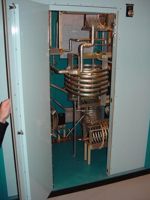
In the following photograph you can see some
large inductors used in a 50 kW radio transmitting circuit.
The inductors are hollow copper tubes coated with silver,
for excellent conductivity at the "skin" of the tube:
The degree to which frequency affects the
effective resistance of a solid wire conductor is impacted
by the gauge of that wire. As a rule, large-gauge wires
exhibit a more pronounced skin effect (change in resistance
from DC) than small-gauge wires at any given frequency. The
equation for approximating skin effect at high frequencies
(greater than 1 MHz) is as follows:
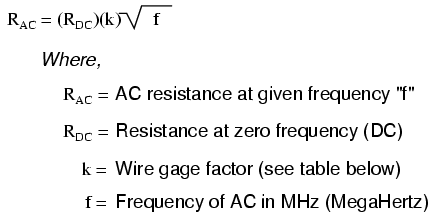
The following table gives approximate values
of "k" factor for various round wire sizes:
Gage size     k factor
======================
4/0 ---------- 124.5
2/0 ---------- 99.0
1/0 ---------- 88.0
2 ------------ 69.8
4 ------------ 55.5
6 ------------ 47.9
8 ------------ 34.8
10 ----------- 27.6
14 ----------- 17.6
18 ----------- 10.9
22 ----------- 6.86
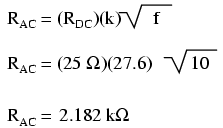
For example, a length of number 10-gauge
wire with a DC end-to-end resistance of 25 Ω would have an
AC (effective) resistance of 2.182 kΩ at a frequency of 10
MHz:
Please remember that this figure is not
impedance, and it does not consider any reactive
effects, inductive or capacitive. This is simply an
estimated figure of pure resistance for the conductor (that
opposition to the AC flow of electrons which does
dissipate power in the form of heat), corrected for skin
effect. Reactance, and the combined effects of reactance and
resistance (impedance), are entirely different matters. |
