Computer simulation
of electric circuits
Computers can be powerful tools if used
properly, especially in the realms of science and
engineering. Software exists for the simulation of electric
circuits by computer, and these programs can be very useful
in helping circuit designers test ideas before actually
building real circuits, saving much time and money.
These same programs can be fantastic aids to
the beginning student of electronics, allowing the
exploration of ideas quickly and easily with no assembly of
real circuits required. Of course, there is no substitute
for actually building and testing real circuits, but
computer simulations certainly assist in the learning
process by allowing the student to experiment with changes
and see the effects they have on circuits. Throughout this
book, I'll be incorporating computer printouts from circuit
simulation frequently in order to illustrate important
concepts. By observing the results of a computer simulation,
a student can gain an intuitive grasp of circuit behavior
without the intimidation of abstract mathematical analysis.
To simulate circuits on computer, I make use
of a particular program called SPICE, which works by
describing a circuit to the computer by means of a listing
of text. In essence, this listing is a kind of computer
program in itself, and must adhere to the syntactical rules
of the SPICE language. The computer is then used to process,
or "run," the SPICE program, which interprets the text
listing describing the circuit and outputs the results of
its detailed mathematical analysis, also in text form. Many
details of using SPICE are described in volume 5
("Reference") of this book series for those wanting more
information. Here, I'll just introduce the basic concepts
and then apply SPICE to the analysis of these simple
circuits we've been reading about.
First, we need to have SPICE installed on
our computer. As a free program, it is commonly available on
the internet for download, and in formats appropriate for
many different operating systems. In this book, I use one of
the earlier versions of SPICE: version 2G6, for its
simplicity of use.
Next, we need a circuit for SPICE to
analyze. Let's try one of the circuits illustrated earlier
in the chapter. Here is its schematic diagram:
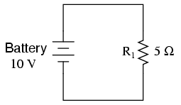
This simple circuit consists of a battery
and a resistor connected directly together. We know the
voltage of the battery (10 volts) and the resistance of the
resistor (5 Ω), but nothing else about the circuit. If we
describe this circuit to SPICE, it should be able to tell us
(at the very least), how much current we have in the circuit
by using Ohm's Law (I=E/R).
SPICE cannot directly understand a schematic
diagram or any other form of graphical description. SPICE is
a text-based computer program, and demands that a circuit be
described in terms of its constituent components and
connection points. Each unique connection point in a circuit
is described for SPICE by a "node" number. Points that are
electrically common to each other in the circuit to be
simulated are designated as such by sharing the same number.
It might be helpful to think of these numbers as "wire"
numbers rather than "node" numbers, following the definition
given in the previous section. This is how the computer
knows what's connected to what: by the sharing of common
wire, or node, numbers. In our example circuit, we only have
two "nodes," the top wire and the bottom wire. SPICE demands
there be a node 0 somewhere in the circuit, so we'll label
our wires 0 and 1:
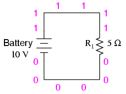
In the above illustration, I've shown
multiple "1" and "0" labels around each respective wire to
emphasize the concept of common points sharing common node
numbers, but still this is a graphic image, not a text
description. SPICE needs to have the component values and
node numbers given to it in text form before any analysis
may proceed.
Creating a text file in a computer involves
the use of a program called a text editor. Similar to
a word processor, a text editor allows you to type text and
record what you've typed in the form of a file stored on the
computer's hard disk. Text editors lack the formatting
ability of word processors (no italic, bold,
or underlined characters), and this is a good thing,
since programs such as SPICE wouldn't know what to do with
this extra information. If we want to create a plain-text
file, with absolutely nothing recorded except the keyboard
characters we select, a text editor is the tool to use.
If using a Microsoft operating system such
as DOS or Windows, a couple of text editors are readily
available with the system. In DOS, there is the old Edit
text editing program, which may be invoked by typing
edit at the command prompt. In Windows
(3.x/95/98/NT/Me/2k/XP), the Notepad text editor is
your stock choice. Many other text editing programs are
available, and some are even free. I happen to use a free
text editor called Vim, and run it under both Windows
95 and Linux operating systems. It matters little which
editor you use, so don't worry if the screenshots in this
section don't look like yours; the important information
here is what you type, not which editor you
happen to use.
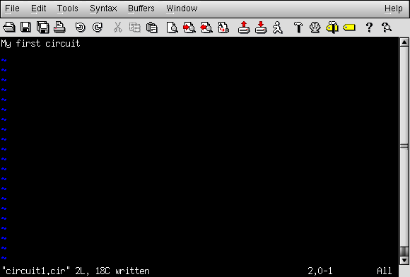
To describe this simple, two-component
circuit to SPICE, I will begin by invoking my text editor
program and typing in a "title" line for the circuit:
We can describe the battery to the computer
by typing in a line of text starting with the letter "v"
(for "Voltage source"), identifying which wire each terminal
of the battery connects to (the node numbers), and the
battery's voltage, like this:
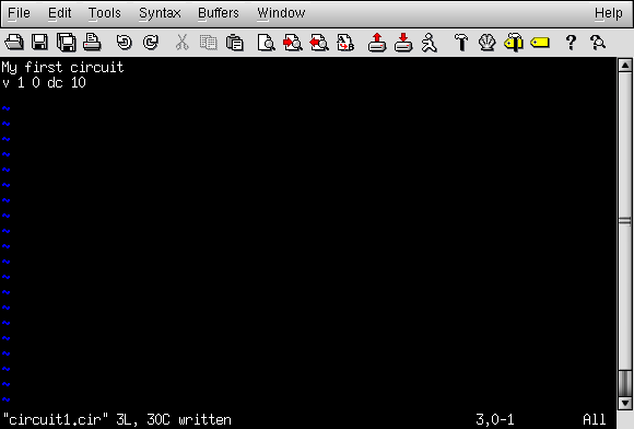
This line of text tells SPICE that we have a
voltage source connected between nodes 1 and 0, direct
current (DC), 10 volts. That's all the computer needs to
know regarding the battery. Now we turn to the resistor:
SPICE requires that resistors be described with a letter
"r," the numbers of the two nodes (connection points), and
the resistance in ohms. Since this is a computer simulation,
there is no need to specify a power rating for the resistor.
That's one nice thing about "virtual" components: they can't
be harmed by excessive voltages or currents!

Now, SPICE will know there is a resistor
connected between nodes 1 and 0 with a value of 5 Ω. This
very brief line of text tells the computer we have a
resistor ("r") connected between the same two nodes
as the battery (1 and 0), with a resistance value of 5 Ω.
If we add an .end statement to this
collection of SPICE commands to indicate the end of the
circuit description, we will have all the information SPICE
needs, collected in one file and ready for processing. This
circuit description, comprised of lines of text in a
computer file, is technically known as a netlist, or
deck:
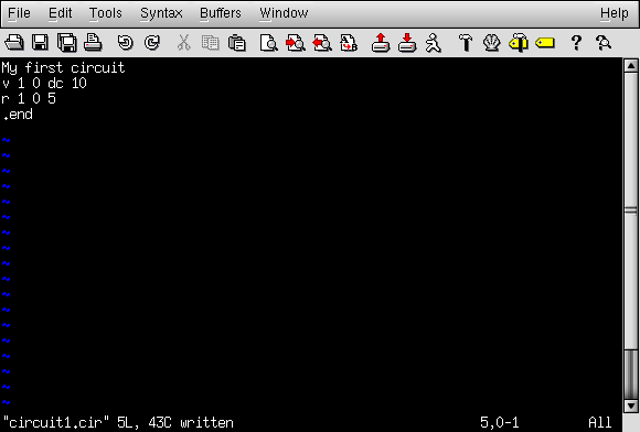
Once we have finished typing all the
necessary SPICE commands, we need to "save" them to a file
on the computer's hard disk so that SPICE has something to
reference to when invoked. Since this is my first SPICE
netlist, I'll save it under the filename "circuit1.cir"
(the actual name being arbitrary). You may elect to name
your first SPICE netlist something completely different,
just as long as you don't violate any filename rules for
your operating system, such as using no more than 8+3
characters (eight characters in the name, and three
characters in the extension: 12345678.123) in DOS.
To invoke SPICE (tell it to process the
contents of the circuit1.cir netlist file), we have
to exit from the text editor and access a command prompt
(the "DOS prompt" for Microsoft users) where we can enter
text commands for the computer's operating system to obey.
This "primitive" way of invoking a program may seem archaic
to computer users accustomed to a "point-and-click"
graphical environment, but it is a very powerful and
flexible way of doing things. Remember, what you're doing
here by using SPICE is a simple form of computer
programming, and the more comfortable you become in giving
the computer text-form commands to follow -- as opposed to
simply clicking on icon images using a mouse -- the more
mastery you will have over your computer.
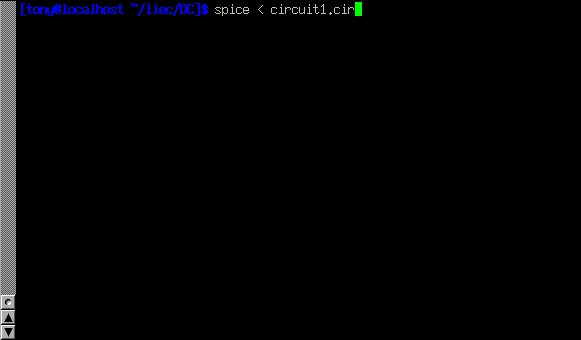
Once at a command prompt, type in this
command, followed by an [Enter] keystroke (this example uses
the filename circuit1.cir; if you have chosen a
different filename for your netlist file, substitute it):
spice < circuit1.cir
Here is how this looks on my computer
(running the Linux operating system), just before I press
the [Enter] key:
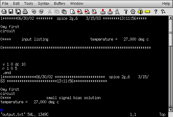
As soon as you press the [Enter] key to
issue this command, text from SPICE's output should scroll
by on the computer screen. Here is a screenshot showing what
SPICE outputs on my computer (I've lengthened the "terminal"
window to show you the full text. With a normal-size
terminal, the text easily exceeds one page length):
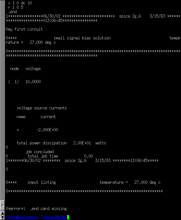
SPICE begins with a reiteration of the
netlist, complete with title line and .end
statement. About halfway through the simulation it displays
the voltage at all nodes with reference to node 0. In this
example, we only have one node other than node 0, so it
displays the voltage there: 10.0000 volts. Then it displays
the current through each voltage source. Since we only have
one voltage source in the entire circuit, it only displays
the current through that one. In this case, the source
current is 2 amps. Due to a quirk in the way SPICE analyzes
current, the value of 2 amps is output as a negative (-) 2
amps.
The last line of text in the computer's
analysis report is "total power dissipation," which in this
case is given as "2.00E+01" watts: 2.00 x 101, or
20 watts. SPICE outputs most figures in scientific notation
rather than normal (fixed-point) notation. While this may
seem to be more confusing at first, it is actually less
confusing when very large or very small numbers are
involved. The details of scientific notation will be covered
in the next chapter of this book.
One of the benefits of using a "primitive"
text-based program such as SPICE is that the text files
dealt with are extremely small compared to other file
formats, especially graphical formats used in other circuit
simulation software. Also, the fact that SPICE's output is
plain text means you can direct SPICE's output to another
text file where it may be further manipulated. To do this,
we re-issue a command to the computer's operating system to
invoke SPICE, this time redirecting the output to a file
I'll call "output.txt":
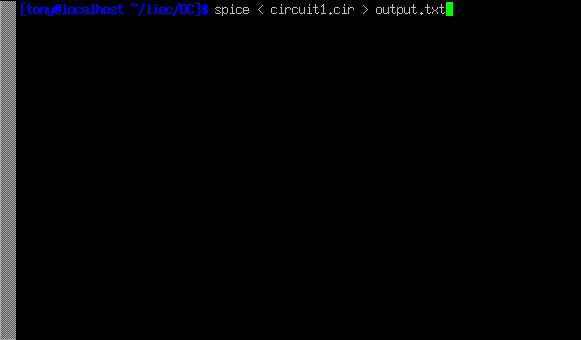
SPICE will run "silently" this time, without
the stream of text output to the computer screen as before.
A new file, output1.txt, will be created, which you
may open and change using a text editor or word processor.
For this illustration, I'll use the same text editor (Vim)
to open this file:
Now, I may freely edit this file, deleting
any extraneous text (such as the "banners" showing date and
time), leaving only the text that I feel to be pertinent to
my circuit's analysis:

Once suitably edited and re-saved under the
same filename (output.txt in this example), the
text may be pasted into any kind of document, "plain text"
being a universal file format for almost all computer
systems. I can even include it directly in the text of this
book -- rather than as a "screenshot" graphic image -- like
this:
my first circuit
v 1 0 dc 10
r 1 0 5
.end
 node   voltage
(  1)   10.0000
voltage source currents
name       current
v        -2.000E+00
total power dissipation 2.00E+01 watts
Incidentally, this is the preferred format
for text output from SPICE simulations in this book series:
as real text, not as graphic screenshot images.
To alter a component value in the
simulation, we need to open up the netlist file (circuit1.cir)
and make the required modifications in the text description
of the circuit, then save those changes to the same
filename, and re-invoke SPICE at the command prompt. This
process of editing and processing a text file is one
familiar to every computer programmer. One of the reasons I
like to teach SPICE is that it prepares the learner to think
and work like a computer programmer, which is good because
computer programming is a significant area of advanced
electronics work.
Earlier we explored the consequences of
changing one of the three variables in an electric circuit
(voltage, current, or resistance) using Ohm's Law to
mathematically predict what would happen. Now let's try the
same thing using SPICE to do the math for us.
If we were to triple the voltage in our last
example circuit from 10 to 30 volts and keep the circuit
resistance unchanged, we would expect the current to triple
as well. Let's try this, re-naming our netlist file so as to
not over-write the first file. This way, we will have
both versions of the circuit simulation stored on the
hard drive of our computer for future use. The following
text listing is the output of SPICE for this modified
netlist, formatted as plain text rather than as a graphic
image of my computer screen:
second example circuit
v 1 0 dc 30
r 1 0 5
.end
node    voltage
(  1)   30.0000
voltage source currents
name       current
v        -6.000E+00
total power dissipation   1.80E+02  watts
Just as we expected, the current tripled
with the voltage increase. Current used to be 2 amps, but
now it has increased to 6 amps (-6.000 x 100).
Note also how the total power dissipation in the circuit has
increased. It was 20 watts before, but now is 180 watts (1.8
x 102). Recalling that power is related to the
square of the voltage (Joule's Law: P=E2/R), this
makes sense. If we triple the circuit voltage, the power
should increase by a factor of nine (32 = 9).
Nine times 20 is indeed 180, so SPICE's output does indeed
correlate with what we know about power in electric
circuits.
If we want to see how this simple circuit
would respond over a wide range of battery voltages, we can
invoke some of the more advanced options within SPICE. Here,
I'll use the ".dc" analysis option to vary the
battery voltage from 0 to 100 volts in 5 volt increments,
printing out the circuit voltage and current at every step.
The lines in the SPICE netlist beginning with a star symbol
("*") are comments. That is, they don't tell
the computer to do anything relating to circuit analysis,
but merely serve as notes for any human being reading the
netlist text.
third example circuit
v 1 0
r 1 0 5
*the ".dc" statement tells spice to sweep the "v" supply
*voltage from 0 to 100 volts in 5 volt steps.
.dc v 0 100 5
.print dc v(1) i(v)
.end
The .print command in this SPICE
netlist instructs SPICE to print columns of numbers
corresponding to each step in the analysis:
v             i(v)
0.000E+00     0.000E+00
5.000E+00    -1.000E+00
1.000E+01    -2.000E+00
1.500E+01    -3.000E+00
2.000E+01    -4.000E+00
2.500E+01    -5.000E+00
3.000E+01    -6.000E+00
3.500E+01    -7.000E+00
4.000E+01    -8.000E+00
4.500E+01    -9.000E+00
5.000E+01    -1.000E+01
5.500E+01    -1.100E+01
6.000E+01    -1.200E+01
6.500E+01    -1.300E+01
7.000E+01    -1.400E+01
7.500E+01    -1.500E+01
8.000E+01    -1.600E+01
8.500E+01    -1.700E+01
9.000E+01    -1.800E+01
9.500E+01    -1.900E+01
1.000E+02    -2.000E+01
If I re-edit the netlist file, changing the
.print command into a .plot command, SPICE
will output a crude graph made up of text characters:
Legend:  + = v#branch
------------------------------------------------------------------------
sweep      v#branch-2.00e+01             -1.00e+01                 0.00e+00
---------------------|------------------------|------------------------|
0.000e+00  0.000e+00 .                        .                        +
5.000e+00 -1.000e+00 .                        .                     +  .
1.000e+01 -2.000e+00 .                        .                   +    .
1.500e+01 -3.000e+00 .                        .                +       .
2.000e+01 -4.000e+00 .                        .              +         .
2.500e+01 -5.000e+00 .                        .           +            .
3.000e+01 -6.000e+00 .                        .         +              .
3.500e+01 -7.000e+00 .                        .      +                 .
4.000e+01 -8.000e+00 .                        .    +                   .
4.500e+01 -9.000e+00 .                        . +                      .
5.000e+01 -1.000e+01 .                        +                        .
5.500e+01 -1.100e+01 .                     +  .                        .
6.000e+01 -1.200e+01 .                   +    .                        .
6.500e+01 -1.300e+01 .                +       .                        .
7.000e+01 -1.400e+01 .              +         .                        .
7.500e+01 -1.500e+01 .           +            .                        .
8.000e+01 -1.600e+01 .         +              .                        .
8.500e+01 -1.700e+01 .      +                 .                        .
9.000e+01 -1.800e+01 .    +                   .                        .
9.500e+01 -1.900e+01 . +                      .                        .
1.000e+02 -2.000e+01 +                        .                        .
---------------------|------------------------|------------------------|
sweep      v#branch-2.00e+01             -1.00e+01                 0.00e+00
In both output formats, the left-hand column
of numbers represents the battery voltage at each interval,
as it increases from 0 volts to 100 volts, 5 volts at a
time. The numbers in the right-hand column indicate the
circuit current for each of those voltages. Look closely at
those numbers and you'll see the proportional relationship
between each pair: Ohm's Law (I=E/R) holds true in each and
every case, each current value being 1/5 the respective
voltage value, because the circuit resistance is exactly 5
Ω. Again, the negative numbers for current in this SPICE
analysis is more of a quirk than anything else. Just pay
attention to the absolute value of each number unless
otherwise specified.
There are even some computer programs able
to interpret and convert the non-graphical data output by
SPICE into a graphical plot. One of these programs is called
Nutmeg, and its output looks something like this:
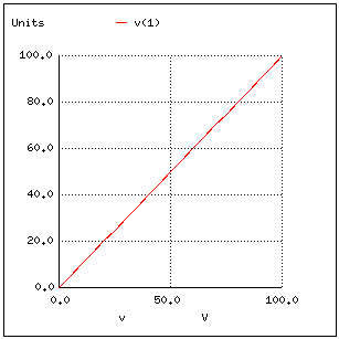
Note how Nutmeg plots the resistor voltage
v(1) (voltage between node 1 and the implied
reference point of node 0) as a line with a positive slope
(from lower-left to upper-right).
Whether or not you ever become proficient at
using SPICE is not relevant to its application in this book.
All that matters is that you develop an understanding for
what the numbers mean in a SPICE-generated report. In the
examples to come, I'll do my best to annotate the numerical
results of SPICE to eliminate any confusion, and unlock the
power of this amazing tool to help you understand the
behavior of electric circuits. |
