Parallel R, L, and C
We can take the same components from the
series circuit and rearrange them into a parallel
configuration for an easy example circuit:
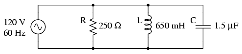
The fact that these components are connected
in parallel instead of series now has absolutely no effect
on their individual impedances. So long as the power supply
is the same frequency as before, the inductive and
capacitive reactances will not have changed at all:
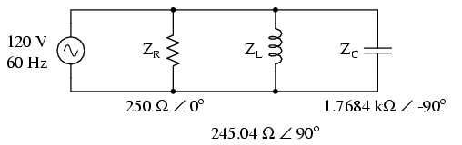
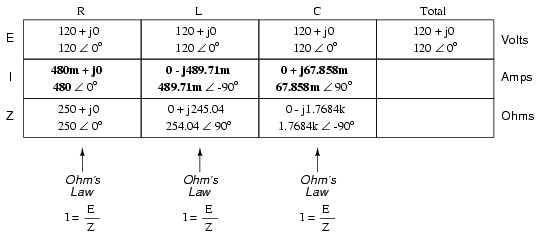
With all component values expressed as
impedances (Z), we can set up an analysis table and proceed
as in the last example problem, except this time following
the rules of parallel circuits instead of series:
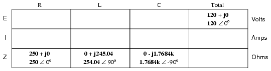
Knowing that voltage is shared equally by
all components in a parallel circuit, we can transfer the
figure for total voltage to all component columns in the
table:
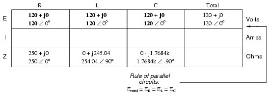
Now, we can apply Ohm's Law (I=E/Z)
vertically in each column to determine current through each
component:
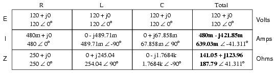
There are two strategies for calculating
total current and total impedance. First, we could calculate
total impedance from all the individual impedances in
parallel (ZTotal = 1/(1/ZR + 1/ZL
+ 1/ZC), and then calculate total current by
dividing source voltage by total impedance (I=E/Z). However,
working through the parallel impedance equation with complex
numbers is no easy task, with all the reciprocations (1/Z).
This is especially true if you're unfortunate enough not to
have a calculator that handles complex numbers and are
forced to do it all by hand (reciprocate the individual
impedances in polar form, then convert them all to
rectangular form for addition, then convert back to polar
form for the final inversion, then invert). The second way
to calculate total current and total impedance is to add up
all the branch currents to arrive at total current (total
current in a parallel circuit -- AC or DC -- is equal to the
sum of the branch currents), then use Ohm's Law to determine
total impedance from total voltage and total current
(Z=E/I).
Either method, performed properly, will
provide the correct answers. Let's try analyzing this
circuit with SPICE and see what happens:
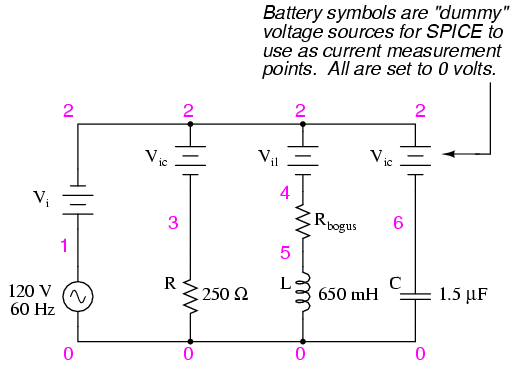
ac r-l-c circuit
v1 1 0 ac 120 sin
vi 1 2 ac 0
vir 2 3 ac 0
vil 2 4 ac 0
rbogus 4 5 1e-12
vic 2 6 ac 0
r1 3 0 250
l1 5 0 650m
c1 6 0 1.5u
.ac lin 1 60 60
.print ac i(vi) i(vir) i(vil) i(vic)
.print ac ip(vi) ip(vir) ip(vil) ip(vic)
.end
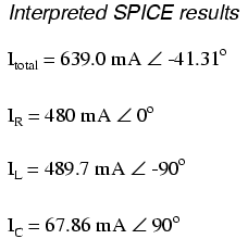
freq          i(vi)       i(vir)      i(vil)      i(vic)
6.000E+01     6.390E-01   4.800E-01   4.897E-01   6.786E-02

freq          ip(vi)      ip(vir)     ip(vil)     ip(vic)
6.000E+01    -4.131E+01   0.000E+00  -9.000E+01   9.000E+01
It took a little bit of trickery to get
SPICE working as we would like on this circuit (installing
"dummy" voltage sources in each branch to obtain current
figures and installing the "dummy" resistor in the inductor
branch to prevent a direct inductor-to-voltage source loop,
which SPICE cannot tolerate), but we did get the proper
readings. Even more than that, by installing the dummy
voltage sources (current meters) in the proper directions,
we were able to avoid that idiosyncrasy of SPICE of printing
current figures 180o out of phase. This way, our
current phase readings came out to exactly match our hand
calculations. |
