In the previous section, we saw a circuit using
one J-K flip-flop that counted backward in a two-bit binary sequence, from
11 to 10 to 01 to 00. Since it would be desirable to have a circuit that
could count forward and not just backward, it would be worthwhile to
examine a forward count sequence again and look for more patterns that might
indicate how to build such a circuit.
Since we know that binary count sequences follow a pattern of octave
(factor of 2) frequency division, and that J-K flip-flop multivibrators set
up for the "toggle" mode are capable of performing this type of frequency
division, we can envision a circuit made up of several J-K flip-flops,
cascaded to produce four bits of output. The main problem facing us is to
determine how to connect these flip-flops together so that they
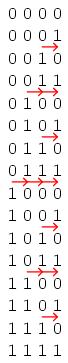
toggle at the right times to produce the proper binary sequence. Examine the
following binary count sequence, paying attention to patterns preceding the
"toggling" of a bit between 0 and 1:

Note that each bit in this four-bit sequence toggles when the bit before
it (the bit having a lesser significance, or place-weight), toggles in a
particular direction: from 1 to 0. Small arrows indicate those points in the
sequence where a bit toggles, the head of the arrow pointing to the previous
bit transitioning from a "high" (1) state to a "low" (0) state:
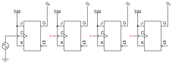
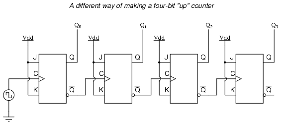
Starting with four J-K flip-flops connected in such a way to always be in
the "toggle" mode, we need to determine how to connect the clock inputs in
such a way so that each succeeding bit toggles when the bit before it
transitions from 1 to 0. The Q outputs of each flip-flop will serve as the
respective binary bits of the final, four-bit count:
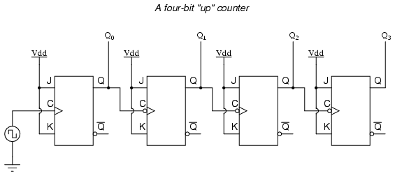
If we used flip-flops with negative-edge triggering (bubble symbols on
the clock inputs), we could simply connect the clock input of each flip-flop
to the Q output of the flip-flop before it, so that when the bit before it
changes from a 1 to a 0, the "falling edge" of that signal would "clock" the
next flip-flop to toggle the next bit:
This circuit would yield the following output waveforms, when "clocked"
by a repetitive source of pulses from an oscillator:
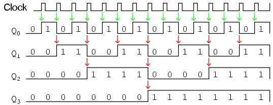
The first flip-flop (the one with the Q0 output), has a
positive-edge triggered clock input, so it toggles with each rising edge of
the clock signal. Notice how the clock signal in this example has a duty
cycle less than 50%. I've shown the signal in this manner for the purpose of
demonstrating how the clock signal need not be symmetrical to obtain
reliable, "clean" output bits in our four-bit binary sequence. In the very
first flip-flop circuit shown in this chapter, I used the clock signal
itself as one of the output bits. This is a bad practice in counter design,
though, because it necessitates the use of a square wave signal with a 50%
duty cycle ("high" time = "low" time) in order to obtain a count sequence
where each and every step pauses for the same amount of time. Using one J-K
flip-flop for each output bit, however, relieves us of the necessity of
having a symmetrical clock signal, allowing the use of practically any
variety of high/low waveform to increment the count sequence.
As indicated by all the other arrows in the pulse diagram, each
succeeding output bit is toggled by the action of the preceding bit
transitioning from "high" (1) to "low" (0). This is the pattern necessary to
generate an "up" count sequence.
A less obvious solution for generating an "up" sequence using
positive-edge triggered flip-flops is to "clock" each flip-flop using the Q'
output of the preceding flip-flop rather than the Q output. Since the Q'
output will always be the exact opposite state of the Q output on a J-K
flip-flop (no invalid states with this type of flip-flop), a high-to-low
transition on the Q output will be accompanied by a low-to-high transition
on the Q' output. In other words, each time the Q output of a flip-flop
transitions from 1 to 0, the Q' output of the same flip-flop will transition
from 0 to 1, providing the positive-going clock pulse we would need to
toggle a positive-edge triggered flip-flop at the right moment:
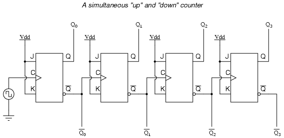
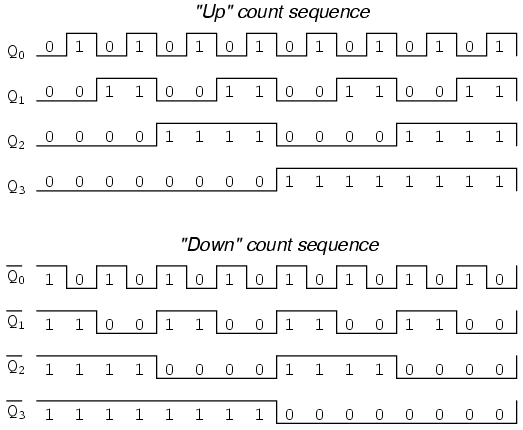
One way we could expand the capabilities of either of these two counter
circuits is to regard the Q' outputs as another set of four binary bits. If
we examine the pulse diagram for such a circuit, we see that the Q' outputs
generate a down-counting sequence, while the Q outputs generate an
up-counting sequence:
Unfortunately, all of the counter circuits shown thusfar share a common
problem: the ripple effect. This effect is seen in certain types of
binary adder and data conversion circuits, and is due to accumulative
propagation delays between cascaded gates. When the Q output of a flip-flop
transitions from 1 to 0, it commands the next flip-flop to toggle. If the
next flip-flop toggle is a transition from 1 to 0, it will command the
flip-flop after it to toggle as well, and so on. However, since there is
always some small amount of propagation delay between the command to toggle
(the clock pulse) and the actual toggle response (Q and Q' outputs changing
states), any subsequent flip-flops to be toggled will toggle some time
after the first flip-flop has toggled. Thus, when multiple bits toggle
in a binary count sequence, they will not all toggle at exactly the same
time:
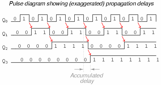
As you can see, the more bits that toggle with a given clock pulse, the
more severe the accumulated delay time from LSB to MSB. When a clock pulse
occurs at such a transition point (say, on the transition from 0111 to
1000), the output bits will "ripple" in sequence from LSB to MSB, as each
succeeding bit toggles and commands the next bit to toggle as well, with a
small amount of propagation delay between each bit toggle. If we take a
close-up look at this effect during the transition from 0111 to 1000, we can
see that there will be false output counts generated in the brief
time period that the "ripple" effect takes place:
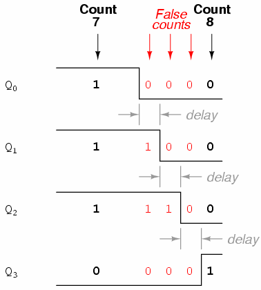
Instead of cleanly transitioning from a "0111" output to a "1000" output,
the counter circuit will very quickly ripple from 0111 to 0110 to 0100 to
0000 to 1000, or from 7 to 6 to 4 to 0 and then to 8.
This behavior earns the counter circuit the name of ripple counter,
or asynchronous counter.
In many applications, this effect is tolerable, since the ripple happens
very, very quickly (the width of the delays has been exaggerated here as an
aid to understanding the effects). If all we wanted to do was drive a set of
light-emitting diodes (LEDs) with the counter's outputs, for example, this
brief ripple would be of no consequence at all. However, if we wished to use
this counter to drive the "select" inputs of a multiplexer, index a memory
pointer in a microprocessor (computer) circuit, or perform some other task
where false outputs could cause spurious errors, it would not be acceptable.
There is a way to use this type of counter circuit in applications sensitive
to false, ripple-generated outputs, and it involves a principle known as
strobing.
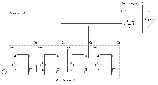
Most decoder and multiplexer circuits are equipped with at least one
input called the "enable." The output(s) of such a circuit will be active
only when the enable input is made active. We can use this enable input to
strobe the circuit receiving the ripple counter's output so that it
is disabled (and thus not responding to the counter output) during the brief
period of time in which the counter outputs might be rippling, and enabled
only when sufficient time has passed since the last clock pulse that all
rippling will have ceased. In most cases, the strobing signal can be the
same clock pulse that drives the counter circuit:
With an active-low Enable input, the receiving circuit will respond to
the binary count of the four-bit counter circuit only when the clock signal
is "low." As soon as the clock pulse goes "high," the receiving circuit
stops responding to the counter circuit's output. Since the counter circuit
is positive-edge triggered (as determined by the first flip-flop
clock input), all the counting action takes place on the low-to-high
transition of the clock signal, meaning that the receiving circuit will
become disabled just before any toggling occurs on the counter circuit's
four output bits. The receiving circuit will not become enabled until the
clock signal returns to a low state, which should be a long enough time
after all rippling has ceased to be "safe" to allow the new count to
have effect on the receiving circuit. The crucial parameter here is the
clock signal's "high" time: it must be at least as long as the maximum
expected ripple period of the counter circuit. If not, the clock signal will
prematurely enable the receiving circuit, while some rippling is still
taking place.
Another disadvantage of the asynchronous, or ripple, counter circuit is
limited speed. While all gate circuits are limited in terms of maximum
signal frequency, the design of asynchronous counter circuits compounds this
problem by making propagation delays additive. Thus, even if strobing is
used in the receiving circuit, an asynchronous counter circuit cannot be
clocked at any frequency higher than that which allows the greatest possible
accumulated propagation delay to elapse well before the next pulse.
The solution to this problem is a counter circuit that avoids ripple
altogether. Such a counter circuit would eliminate the need to design a "strobing"
feature into whatever digital circuits use the counter output as an input,
and would also enjoy a much greater operating speed than its asynchronous
equivalent. This design of counter circuit is the subject of the next
section.
REVIEW: An "up" counter may be made by connecting the clock inputs of
positive-edge triggered J-K flip-flops to the Q' outputs of the preceding
flip-flops. Another way is to use negative-edge triggered flip-flops,
connecting the clock inputs to the Q outputs of the preceding flip-flops.
In either case, the J and K inputs of all flip-flops are connected to Vcc
or Vdd so as to always be "high." Counter circuits made from cascaded J-K flip-flops where each clock
input receives its pulses from the output of the previous flip-flop
invariably exhibit a ripple effect, where false output counts are
generated between some steps of the count sequence. These types of counter
circuits are called asynchronous counters, or ripple counters.
Strobing is a technique applied to circuits receiving the
output of an asynchronous (ripple) counter, so that the false counts
generated during the ripple time will have no ill effect. Essentially, the
enable input of such a circuit is connected to the counter's clock
pulse in such a way that it is enabled only when the counter outputs are
not changing, and will be disabled during those periods of changing
counter outputs where ripple occurs.
|
