Any kind of switch contact can be designed so that the
contacts "close" (establish continuity) when actuated, or "open" (interrupt
continuity) when actuated. For switches that have a spring-return mechanism
in them, the direction that the spring returns it to with no applied force
is called the normal position. Therefore, contacts that are open in
this position are called normally open and contacts that are closed
in this position are called normally closed.
For process switches, the normal position, or state, is that which the
switch is in when there is no process influence on it. An easy way to figure
out the normal condition of a process switch is to consider the state of the
switch as it sits on a storage shelf, uninstalled. Here are some examples of
"normal" process switch conditions:
Speed switch: Shaft not turning Pressure switch: Zero applied pressure Temperature switch: Ambient (room) temperature Level switch: Empty tank or bin Flow switch: Zero liquid flow
It is important to differentiate between a switch's "normal" condition
and its "normal" use in an operating process. Consider the example of a
liquid flow switch that serves as a low-flow alarm in a cooling water
system. The normal, or properly-operating, condition of the cooling water
system is to have fairly constant coolant flow going through this pipe. If
we want the flow switch's contact to close in the event of a loss of
coolant flow (to complete an electric circuit which activates an alarm
siren, for example), we would want to use a flow switch with
normally-closed rather than normally-open contacts. When there's
adequate flow through the pipe, the switch's contacts are forced open; when
the flow rate drops to an abnormally low level, the contacts return to their
normal (closed) state. This is confusing if you think of "normal" as being
the regular state of the process, so be sure to always think of a switch's
"normal" state as that which it's in as it sits on a shelf.
The schematic symbology for switches vary according to the switch's
purpose and actuation. A normally-open switch contact is drawn in such a way
as to signify an open connection, ready to close when actuated. Conversely,
a normally-closed switch is drawn as a closed connection which will be
opened when actuated. Note the following symbols:
 There is also a generic symbology for any switch contact,
using a pair of vertical lines to represent the contact points in a switch.
Normally-open contacts are designated by the lines not touching, while
normally-closed contacts are designated with a diagonal line bridging
between the two lines. Compare the two:
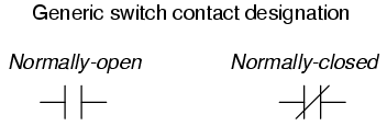 The switch on the left will close when actuated, and will
be open while in the "normal" (unactuated) position. The switch on the right
will open when actuated, and is closed in the "normal" (unactuated)
position. If switches are designated with these generic symbols, the type of
switch usually will be noted in text immediately beside the symbol. Please
note that the symbol on the left is not to be confused with that of a
capacitor. If a capacitor needs to be represented in a control logic
schematic, it will be shown like this:
 In standard electronic symbology, the figure shown above is
reserved for polarity-sensitive capacitors. In control logic symbology, this
capacitor symbol is used for any type of capacitor, even when the
capacitor is not polarity sensitive, so as to clearly distinguish it from a
normally-open switch contact.
With multiple-position selector switches, another design factor must be
considered: that is, the sequence of breaking old connections and making new
connections as the switch is moved from position to position, the moving
contact touching several stationary contacts in sequence.
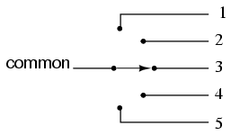 The selector switch shown above switches a common contact
lever to one of five different positions, to contact wires numbered 1
through 5. The most common configuration of a multi-position switch like
this is one where the contact with one position is broken before the
contact with the next position is made. This configuration is called
break-before-make. To give an example, if the switch were set at
position number 3 and slowly turned clockwise, the contact lever would move
off of the number 3 position, opening that circuit, move to a position
between number 3 and number 4 (both circuit paths open), and then touch
position number 4, closing that circuit.
There are applications where it is unacceptable to completely open the
circuit attached to the "common" wire at any point in time. For such an
application, a make-before-break switch design can be built, in which
the movable contact lever actually bridges between two positions of contact
(between number 3 and number 4, in the above scenario) as it travels between
positions. The compromise here is that the circuit must be able to tolerate
switch closures between adjacent position contacts (1 and 2, 2 and 3, 3 and
4, 4 and 5) as the selector knob is turned from position to position. Such a
switch is shown here:
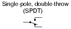
 When movable contact(s) can be brought into one of several
positions with stationary contacts, those positions are sometimes called
throws. The number of movable contacts is sometimes called poles.
Both selector switches shown above with one moving contact and five
stationary contacts would be designated as "single-pole, five-throw"
switches.
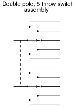
If two identical single-pole, five-throw switches were mechanically
ganged together so that they were actuated by the same mechanism, the whole
assembly would be called a "double-pole, five-throw" switch:
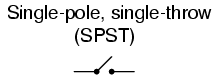
 Here are a few common switch configurations and their
abbreviated designations:


-
REVIEW:
-
The normal state of a switch is that where it is
unactuated. For process switches, this is the condition it's in when
sitting on a shelf, uninstalled.
-
A switch that is open when unactuated is called
normally-open. A switch that is closed when unactuated is called
normally-closed. Sometimes the terms "normally-open" and
"normally-closed" are abbreviated N.O. and N.C., respectively.
-
The generic symbology for N.O. and N.C. switch contacts is
as follows:
Multiposition switches can be either break-before-make (most common)
or make-before-break. The "poles" of a switch refers to the number of moving contacts, while
the "throws" of a switch refers to the number of stationary contacts per
moving contact.
|
