|
 Most robots of today are nearly deaf and blind. Sensors can provide
some limited feedback to the robot so it can do its job. Compared to
the senses and abilities of even the simplest living things, robots
have a very long way to go. Most robots of today are nearly deaf and blind. Sensors can provide
some limited feedback to the robot so it can do its job. Compared to
the senses and abilities of even the simplest living things, robots
have a very long way to go.
The sensor sends information, in the form of electronic signals
back to the cfontroller. Sensors also give the robot controller
information about its surroundings and lets it know the exact position
of the arm, or the state of the world around it.
Sight, sound, touch, taste, and smell are the kinds of information
we get from our world. Robots can be designed and programmed to get
specific information that is beyond what our 5 senses can tell us. For
instance, a robot sensor might "see" in the dark, detect tiny amounts
of invisible radiation or measure movement that is too small or fast
for the human eye to see.
Here are some things sensors are used
for:
|
|
|
| Contact |
Bump, Switch |
| Distance |
Ultrasound, Radar,
Infra Red |
| Light Level |
Photo Cells, Cameras |
| Sound Level |
microphones |
| Strain |
Strain Gauges |
| Rotation |
Encoders |
| Magnetism |
Compasses |
| Smell |
Chemical |
| Temperature |
Thermal, Infra Red |
| Inclination |
Inclinometers,
Gyroscope |
| Pressure |
Pressure Gauges |
| Altitude |
Altimeters |
Sensors can be made simple and
complex, depending on how much information needs to be stored. A
switch is a simple on/off sensor used for turning the robot on and
off. A human retina is a complex sensor that uses more than a hundred
million photosensitive elements (rods and cones). Sensors provide
information to the robots brain, which can be treated in various
ways. For example, we can simply react to the sensor output:
if the switch is open, if the switch is closed, go.
To figure out if the switch is open
or closed, you will need to measure the voltage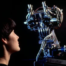 going through the circuit, that's electronics. Now lets say that you
have a microphone and you want to recognize a voice and separate it
from noise; that's signal processing. Now you have a camera, and you
want to take the pre-processed image and now you need to figure out
what those objects are, perhaps by comparing them to a large library
of drawings; that's computation. Sensory data processing is a very
complex thing to try and do but the robot needs this in order to have
a "brain". The brain has to have analog or digital processing
capabilities, wires to connect everything, support electronics to go
with the computer, and batteries to provide power for the whole thing,
in order to process the sensory data. Perception requires the robot
to have sensors (power and electronics), computation (more power and
electronics, and connectors (to connect it all).
going through the circuit, that's electronics. Now lets say that you
have a microphone and you want to recognize a voice and separate it
from noise; that's signal processing. Now you have a camera, and you
want to take the pre-processed image and now you need to figure out
what those objects are, perhaps by comparing them to a large library
of drawings; that's computation. Sensory data processing is a very
complex thing to try and do but the robot needs this in order to have
a "brain". The brain has to have analog or digital processing
capabilities, wires to connect everything, support electronics to go
with the computer, and batteries to provide power for the whole thing,
in order to process the sensory data. Perception requires the robot
to have sensors (power and electronics), computation (more power and
electronics, and connectors (to connect it all).
Switches are the simplest sensors
of all. They work without processing, at the electronics (circuit)
level. Their general underlying principle is that of an open vs.
closed circuit. If a switch is open, no current can flow; if it is
closed, current can flow and be detected. This simple principle can
(and is) used in a wide variety of ways.
Switch sensors can be used in a variety
of ways:
-
contact sensors: detect when
the sensor has contacted another object (e.g., triggers when a robot
hits a wall or grabs an object; these can even be whiskers)
-
limit sensors: detect when a
mechanism has moved to the end of its range
-
shaft encoder sensors:
detects how many times a shaft turns by having a switch click
(open/close) every time the shaft turns (e.g., triggers for each
turn, allowing for counting rotations)
There are many common switches:
button switches, mouse switches, key board keys, phone keys, and
others. Depending on how a switch is wired, it can be normally open
or normally closed. This would of course depend on your robot's
electronics, mechanics, and its task. The simplest yet extremely
useful sensor for a robot is a "bump switch" that tells it when it's
bumped into something, so it can back up and turn away. Even for such
a simple idea, there are many different ways of implementation.
Switches measure physical contact
and light sensors measure the amount of light impacting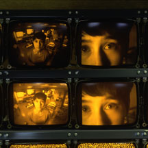 a photocell, which is basically a resistive sensor. The resistance of
a photocell is low when it is brightly illuminated, i.e., when it is
very light; it is high when it is dark. In that sense, a light sensor
is really a "dark" sensor. In setting up a photocell sensor, you will
end up using the equations we learned above, because you will need to
deal with the relationship of the photocell resistance photo, and the
resistance and voltage in your electronics sensor circuit. Of course
since you will be building the electronics and writing the program to
measure and use the output of the light sensor, you can always
manipulate it to make it simpler and more intuitive. What surrounds a
light sensor affects its properties. The sensor can be shielded and
positioned in various ways. Multiple sensors can be arranged in
useful configurations and isolate them from each other with shields.
a photocell, which is basically a resistive sensor. The resistance of
a photocell is low when it is brightly illuminated, i.e., when it is
very light; it is high when it is dark. In that sense, a light sensor
is really a "dark" sensor. In setting up a photocell sensor, you will
end up using the equations we learned above, because you will need to
deal with the relationship of the photocell resistance photo, and the
resistance and voltage in your electronics sensor circuit. Of course
since you will be building the electronics and writing the program to
measure and use the output of the light sensor, you can always
manipulate it to make it simpler and more intuitive. What surrounds a
light sensor affects its properties. The sensor can be shielded and
positioned in various ways. Multiple sensors can be arranged in
useful configurations and isolate them from each other with shields.
Just like switches, light sensors can
be used in many different ways:
-
Light sensors can measure:
-
light intensity (how light/dark it
is)
-
differential intensity (difference
between photocells)
-
break-beam (change/drop in
intensity)
-
Light sensors can be shielded and
focused in different ways
-
Their position and directionality on
a robot can make a great deal of difference and impact
"Normal" light emanating from a
source is non-polarized, which means it travels at all orientations
with respect to the horizon. However, if there is a polarizing filter
in front of a light source, only the light waves of a given
orientation of the filter will pass through. This is useful because
now we can manipulate this remaining light with other filters; if we
put it through another filter with the same characteristic plane,
almost all of it will get through. But, if we use a perpendicular
filter (one with a 90-degree relative characteristic angle), we will
block all of the light. Polarized light can be used to make
specialized sensors out of simple photocells; if you put a filter in
front of a light source and the same or a different filter in front of
a photocell, you can cleverly manipulate what and how much light you
detect.
We said earlier that a photocell is
a resistive device. We can also sense resistance in response to other
physical properties, such as bending. The resistance of the
device increases with the amount it is bent. These bend sensors were
originally developed for video game control (for example, Nintendo
Powerglove), and are generally quite useful. Notice that repeated
bending will wear out the sensor. Not surprisingly, a bend sensor is
much less robust than light sensors, although they use the same
underlying resistive principle.
These devices are very common for
manual tuning; you have probably seen them in some controls (such as
volume and tone on stereos). Typically called pots, they
allow the user to manually adjust the resistance. The general idea is
that the device consists of a movable tap along two fixed ends. As
the tap is moved, the resistance changes. As you can imagine, the
resistance between the two ends is fixed, but the resistance between
the movable part and either end varies as the part is moved. In
robotics, pots are commonly used to sense and tune position for
sliding and rotating mechanisms.
-
All of the sensors we described exist in biological systems
-
Touch/contact sensors with much more precision and complexity in all species
-
Bend/resistance receptors in muscles
We mentioned that if we use a light
bulb in combination with a photocell, we can make a break-beam sensor.
This idea is the underlying principle in reflective optosensors: the
sensor consists of an emitter and a detector. Depending of the
arrangement of those two relative to each other, we can get two types
of sensors:
reflectance sensors (the
emitter and the detector are next to each other, separated by a
barrier; objects are detected when the light is reflected off them
and back into the detector)
break-beam sensors (the
emitter and the detector face each other; objects are detected if
they interrupt the beam of light between the emitter and the
detector)
The emitter is usually made out of
a light-emitting diode (an LED), and the detector is usually a
photodiode/phototransistor.
Note that these are not the same
technology as resistive photocells. Resistive photocells are nice and
simple, but their resistive properties make them slow; photodiodes and
photo-transistors are much faster and therefore the preferred type of
technology.
What can you do with this simple idea
of light reflectivity? Quite a lot of useful things:
-
object presence detection
-
object distance detection
-
surface feature detection
(finding/following markers/tape)
-
wall/boundary tracking
-
rotational shaft encoding (using
encoder wheels with ridges or black & white color)
-
bar code decoding
Note, however, that light
reflectivity depends on the color (and other properties) of a surface.
A light surface will reflect light better than a dark one, and a black
surface may not reflect it at all, thus appearing invisible to a light
sensor. Therefore, it may be harder (less reliable) to detect darker
objects this way than lighter ones. In the case of object distance,
lighter objects that are farther away will seem closer than darker
objects that are not as far away. This gives you an idea of how the
physical world is partially-observable. Even though we have useful
sensors, we do not have complete and completely accurate information.
Another source of noise in light
sensors is ambient light. The best thing to do is subtract the ambient
light level out of the sensor reading, in order to detect the actual
change in the reflected light, not the ambient light. How is that
done? By taking two (or more, for higher accuracy) readings of the
detector, one with the emitter on, and one with it off, and
subtracting the two values from each other. The result is the ambient
light level, which can then be subtracted from future readings. This
process is called sensor calibration. Of course, remember
that ambient light levels can change, so the sensors may need to be
calibrated repeatedly.
We already talked about the idea of
break-beam sensors. In general, any pair of compatible
emitter-detector devices can be used to produce such a sensors:
-
an incandescent flashlight bulb
and a photocell
-
red LEDs and
visible-light-sensitive photo-transistors
-
or infra-red IR emitters and
detectors
Shaft encoders measure
the angular rotation of an axle providing position and/or velocity
info. For example, a speedometer measures how fast the wheels of a
vehicle are turning, while an odometer measures the number of
rotations of the wheels.
In order to detect a
complete or partial rotation, we have to somehow mark the turning
element. This is usually done by attaching a round disk to the shaft,
and cutting notches into it. A light emitter and detector are placed
on each side of the disk, so that as the notch passes between them,
the light passes, and is detected; where there is no notch in the
disk, no light passes.
If there is only one
notch in the disk, then a rotation is detected as it happens. This is
not a very good idea, since it allows only a low level of resolution
for measuring speed: the smallest unit that can be measured is a full
rotation. Besides, some rotations might be missed due to noise.
Usually, many notches
are cut into the disk, and the light hits impacting the detector are
counted. (You can see that it is important to have a fast sensor here,
if the shaft turns very quickly.)
An alternative to
cutting notches in the disk is to paint the disk with black
(absorbing, non-reflecting) and white (highly reflecting) wedges, and
measure the reflectance. In this case, the emitter and the detector
are on the same side of the disk.
In either case, the
output of the sensor is going to be a wave function of the light
intensity. This can then be processes to produce the speed, by
counting the peaks of the waves.
Note that shaft encoding
measures both position and rotational velocity, by subtracting the
difference in the position readings after each time interval.
Velocity, on the other hand, tells us how fast a robot is moving, or
if it is moving at all. There are multiple ways to use this measure:
We can combine the position and
velocity information to do more sophisticated things:
Note, however, that doing such
things is quite difficult, because wheels tend to slip (effector noise
and error) and slide and there is usually some slop and backlash in
the gearing mechanism. Shaft encoders can provide feedback to correct
the errors, but having some error is unavoidable.
So far, we've talked
about detecting position and velocity, but did not talk about
direction of rotation. Suppose the wheel suddenly changes the
direction of rotation; it would be useful for the robot to detect
that.
An example of a common
system that needs to measure position, velocity, and direction is a
computer mouse. Without a measure of direction, a mouse is pretty
useless. How is direction of rotation measured?
Quadrature shaft encoding is an
elaboration of the basic break-beam idea; instead of using only one
sensor, two are needed. The encoders are aligned so that their two
data streams coming from the detector and one quarter cycle
(90-degrees) out of phase, thus the name "quadrature". By comparing
the output of the two encoders at each time step with the output of
the previous time step, we can tell if there is a direction change.
When the two are sampled at each time step, only one of them will
change its state (i.e., go from on to off) at a time, because they are
out of phase. Which one does it determines which direction the shaft
is rotating. Whenever a shaft is moving in one direction, a counter is
incremented, and when it turns in the opposite direction, the counter
is decremented, thus keeping track of the overall position.
Other uses of quadrature shaft
encoding are in robot arms with complex joints (such as rotary/ball
joints; think of your knee or shoulder), Cartesian robots (and large
printers) where an arm/rack moves back and forth along an axis/gear.
We mentioned that ambient light is
a problem because it interferes with the emitted light from a light
sensor. One way to get around this problem is to emit modulated
light, i.e., to rapidly turn the emitter on and off. Such a
signal is much easier and more reliably detected by a demodulator,
which is tuned to the particular frequency of the modulated light. Not
surprisingly, a detector needs to sense several on-flashes in a row in
order to detect a signal, i.e., to detect its frequency. This is a
small point, but it is important in writing demodulator code.
The idea of modulated IR light is
commonly used; for example in household remote controls.
Modulated light sensors
are generally more reliable than basic light sensors. They can be used
for the same purposes: detecting the presence of an object measuring the distance to a nearby
object (clever electronics required, see your course notes)
Infra red sensors are a type of
light sensors, which function in the infra red part of the frequency
spectrum. IR sensors consist are active sensors: they consist of an
emitter and a receiver. IR sensors are used in the same ways that
visible light sensors are that we have discussed so far: as
break-beams and as reflectance sensors. IR is preferable to visible
light in robotics (and other) applications because it suffers a bit
less from ambient interference, because it can be easily modulated,
and simply because it is not visible.
Modulated infra red can be used as
a serial line for transmitting messages. This is is fact how IR modems
work. Two basic methods exist:
-
bit frames (sampled in the middle
of each bit; assumes all bits take the same amount of time to
transmit)
-
bit intervals (more common in
commercial use; sampled at the falling edge, duration of interval
between sampling determines whether it's a 0 or 1)
As we mentioned before,
ultrasound sensing is based on the time-of-flight principle. The
emitter produces a sonar "chirp" of sound, which travels away from the
source, and, if it encounters barriers, reflects from them and returns
to the receiver (microphone). The amount of time it takes for the
sound beam to come back is tracked (by starting a timer when the
"chirp" is produced, and stopping it when the reflected sound
returns), and is used to compute the distance the sound traveled. This
is possible (and quite easy) because we know how fast sound travels;
this is a constant, which varies slightly based on ambient
temperature.
At room temperature,
sound travels at 1.12 feet per millisecond. Another way to put it that
sound travels at 0.89 milliseconds per foot. This is a useful constant
to remember.
The process of finding one's
location based on sonar is called echolocation. The
inspiration for ultrasound sensing comes from nature; bats use
ultrasound instead of vision (this makes sense; they live in very dark
caves where vision would be largely useless). Bat sonars are extremely
sophisticated compared to artificial sonars; they involve numerous
different frequencies, used for finding even the tiniest fast-flying
prey, and for avoiding hundreds of other bats, and communicating for
finding mates.
A major disadvantage of ultrasound
sensing is its susceptibility to specular reflection (specular
reflection means reflection from the outer surface of the object).
While the sonar sensing principle is based on the sound wave
reflecting from surfaces and returning to the receiver, it is
important to remember that the sound wave will not necessarily bounce
off the surface and "come right back." In fact, the direction of
reflection depends on the incident angle of the sound beam and the
surface. The smaller the angle, the higher the probability that the
sound will merely "graze" the surface and bounce off, thus not
returning to the emitter, in turn generating a false long/far-away
reading. This is often called specular reflection, because smooth
surfaces, with specular properties, tend to aggravate this reflection
problem. Coarse surfaces produce more irregular reflections, some of
which are more likely to return to the emitter. (For example, in our
robotics lab on campus, we use sonar sensors, and we have lined one
part of the test area with cardboard, because it has much better sonar
reflectance properties than the very smooth wall behind it.)
In summary, long sonar
readings can be very inaccurate, as they may result from false rather
than accurate reflections. This must be taken into account when
programming robots, or a robot may produce very undesirable and unsafe
behavior. For example, a robot approaching a wall at a steep angle may
not see the wall at all, and collide with it!
Nonetheless, sonar
sensors have been successfully used for very sophisticated robotics
applications, including terrain and indoor mapping, and remain a very
popular sensor choice in mobile robotics.
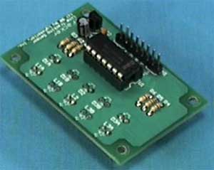
The first commercial ultrasonic
sensor was produced by Polaroid, and used to automatically measure the
distance to the nearest object (presumably which is being
photographed). These simple Polaroid sensors still remain the most
popular off-the-shelf sonars (they come with a processor board that
deals with the analog electronics). Their standard properties include:
Polaroid sensors can be
combined into phased arrays to create more sophisticated and more
accurate sensors.
One can find ultrasound used in a
variety of other applications; the best known one is ranging in
submarines. The sonars there have much more focused and have
longer-range beams. Simpler and more mundane applications involve
automated "tape-measures", height measures, burglar alarms, etc.
So far, we have talked
about relatively simple sensors. They were simple in terms of
processing of the information they returned. Now we turn to machine
vision, i.e., to cameras as sensors.
Cameras, of course,
model biological eyes. Needless to say, all biological eyes are more
complex than any camera we know today, but, as you will see, the
cameras and machine vision systems that process their perceptual
information, are not simple at all! In fact, machine vision is such a
challenging topic that it has historically been a separate branch of
Artificial Intelligence.
The general principle of a camera
is that of light, scattered from objects in the environment (those are
called the scene), goes through an opening ("iris", in the
simplest case a pin hole, in the more sophisticated case a
lens), and impinging on what is called the image plane.
In biological systems, the image plane is the retina, which
is attached to numerous rods and cones (photosensitive elements)
which, in turn, are attached to nerves which perform so-called "early
vision", and then pass information on throughout the brain to do
"higher-level" vision processing. As we mentioned before, a very large
percentage of the human (and other animal) brain is dedicated to
visual processing, so this is a highly complex endeavor.
In cameras, instead of having
photosensitive rhodopsin and rods and cones, we use silver halides on
photographic film, or silicon circuits in charge-coupled devices (CCD)
cameras. In all cases, some information about the incoming light
(e.g., intensity, color) is detected by these photosensitive elements
on the image plane.
In machine vision, the computer
must make sense out of the information it gets on the image plane. If
the camera is very simple, and uses a tiny pin hole, then some
computation is required to compute the projection of the objects from
the environment onto the image plane (note, they will be inverted). If
a lens is involved (as in vertebrate eyes and real cameras), then more
light can get in, but at the price of being focused; only objects a
particular range of distances from the lens will be in focus. This
range of distances is called the camera's depth of field.
The image plane is usually
subdivided into equal parts, called pixels, typically
arranged in a rectangular grid. In a typical camera there are 512 by
512 pixels on the image plane (for comparison, there are 120 x 10^6
rods and 6 x 10^6 cones in the eye, arranged hexagonally). Let's call
the projection on the image plane the image.
The brightness of each pixel in the
image is proportional to the amount of light directed toward the
camera by the surface patch of the object that projects to that pixel.
(This of course depends on the reflectance properties of the surface
patch, the position and distribution of the light sources in the
environment, and the amount of light reflected from other objects in
the scene onto the surface patch.) As it turns out, brightness of a
patch depends on two kinds of reflections, one being specular (off the
surface, as we saw before), and the other being diffuse (light that
penetrates into the object, is absorbed, and then re-emitted). To
correctly model light reflection, as well as reconstruct the scene,
all these properties are necessary.
Let us suppose that we are dealing
with a black and white camera with a 512 x 512 pixel image plane. Now
we have an image, which is a collection of those pixels, each of which
is an intensity between white and black. To find an object in that
image (if there is one, we of course don't know a priori),
the typical first step ("early vision") is to do edge detection,
i.e., find all the edges. How do we recognize them? We define edges as
curves in the image plane across which there is significant change in
the brightness.
A simple approach would
be to look for sharp brightness changes by differentiating the image
and look for areas where the magnitude of the derivative is large.
This almost works, but unfortunately it produces all sorts of spurious
peaks, i.e., noise. Also, we cannot inherently distinguish changes in
intensities due to shadows from those due to physical objects. But
let's forget that for now and think about noise. How do we deal with
noise?
We do smoothing, i.e., we
apply a mathematical procedure called convolution, which
finds and eliminates the isolated peaks. Convolution, in effect,
applies a filter to the image. In fact, in order to find
arbitrary edges in the image, we need to convolve the image with many
filters with different orientations. Fortunately, the relatively
complicated mathematics involved in edge detection has been well
studied, and by now there are standard and preferred approaches to
edge detection.
Once we have edges, the next thing
to do is try to find objects among all those edges. Segmentation
is the process of dividing up or organizing the image into parts that
correspond to continuous objects. But how do we know which lines
correspond to which objects, and what makes an object? There are
several cues we can use to detect objects:
-
We can have stored models
of line-drawings of objects (from many possible angles, and at many
different possible scales!), and then compare those with all
possible combinations of edges in the image. Notice that this is a
very computationally intensive and expensive process. This general
approach, which has been studied extensively, is called
model-based vision.
-
We can take advantage of
motion. If we look at an image at two consecutive time-steps,
and we move the camera in between, each continuous solid objects
(which obeys physical laws) will move as one, i.e., its brightness
properties will be conserved. This hives us a hint for finding
objects, by subtracting two images from each other. But notice that
this also depends on knowing well how we moved the camera relative
to the scene (direction, distance), and that nothing was moving in
the scene at the time. This general approach, which has also been
studied extensively, is called motion vision.
-
We can use stereo (i.e.,
binocular stereopsis, two eyes/cameras/points of view). Just
like with motion vision above, but without having to actually move,
we get two images, which we can subtract from each other, if we know
what the disparity between them should be, i.e., if we know
how the two cameras are organized/positioned relative to each other.
-
We can use texture.
Patches that have uniform texture are consistent, and have almost
identical brightness, so we can assume they come from the same
object. By extracting those we can get a hint about what parts may
belong to the same object in the scene.
-
We can also use shading
and contours in a similar fashion. And there are many other
methods, involving object shape and projective invariants,
etc.
Note that all of the
above strategies are employed in biological vision. It's hard to
recognize unexpected objects or totally novel ones (because we don't
have the models at all, or not at the ready). Movement helps catch our
attention. Stereo, i.e., two eyes, is critical, and all carnivores use
it (they have two eyes pointing in the same direction, unlike
herbivores). The brain does an excellent job of quickly extracting the
information we need for the scene.
Machine vision has the same task of
doing real-time vision. But this is, as we have seen, a very difficult
task. Often, an alternative to trying to do all of the steps above in
order to do object recognition, it is possible to simplify
the vision problem in various ways:
-
Use color; look for
specifically and uniquely colored objects, and recognize them that
way (such as stop signs, for example)
-
Use a small image plane; instead
of a full 512 x 512 pixel array, we can reduce our view to much
less, for example just a line (that's called a linear CCD).
Of course there is much less information in the image, but if we are
clever, and know what to expect, we can process what we see quickly
and usefully.
-
Use other, simpler and faster,
sensors, and combine those with vision. For example, IR cameras
isolate people by body-temperature. Grippers allow us to touch and
move objects, after which we can be sure they exist.
-
Use information about
the environment; if you know you will be driving on the road which
has white lines, look specifically for those lines at the right
places in the image. This is how first and still fastest road and
highway robotic driving is done.
Those and many other
clever techniques have to be employed when we consider how important
it is to "see" in real-time. Consider highway driving as an important
and growing application of robotics and AI. Everything is moving so
quickly, that the system must perceive and act in time to react
protectively and safely, as well as intelligently.
Now that you know how
complex vision is, you can see why it was not used on the first
robots, and it is still not used for all applications, and definitely
not on simple robots. A robot can be extremely useful without vision,
but some tasks demand it. As always, it is critical to think about the
proper match between the robot's sensors and the task. |