|
Actuators, also known as drives, are
mechanisms for getting robots to move. Most actuators are powered by
pneumatics (a ir
pressure), hydraulics (fluid pressure), or motors (electric
current). Most actuation uses electromagnetic motors and gears but
there have been frequent uses of other forms of actuation including
NiTinOL"muscle-wires" and inexpensive Radio Control servos. To get a
motor under computer control, different motor types and actuator types
are used. Some of the motor types are Synchronous, Stepper, AC servo,
Brushless DC servo, and Brushed DC servo. Radio Control servos for
model airplanes, cars and other vehicles are light, rugged, cheap and
fairly easy to interface. Some of the units can provide very high
torque speed. A Radio Control servo can be controlled from a parallel
port. With one of the PC�s internal timers cranked up, it is possible
to control eight servos from a common parallel port with nothing but a
simple interrupt service routine and a cable. In fact, power can be
pulled from the disk drive power connector and the PC can run all
servos directly with no additional hardware. The only down side is
that the PC wastes some processing power servicing the interrupt
handler. ir
pressure), hydraulics (fluid pressure), or motors (electric
current). Most actuation uses electromagnetic motors and gears but
there have been frequent uses of other forms of actuation including
NiTinOL"muscle-wires" and inexpensive Radio Control servos. To get a
motor under computer control, different motor types and actuator types
are used. Some of the motor types are Synchronous, Stepper, AC servo,
Brushless DC servo, and Brushed DC servo. Radio Control servos for
model airplanes, cars and other vehicles are light, rugged, cheap and
fairly easy to interface. Some of the units can provide very high
torque speed. A Radio Control servo can be controlled from a parallel
port. With one of the PC�s internal timers cranked up, it is possible
to control eight servos from a common parallel port with nothing but a
simple interrupt service routine and a cable. In fact, power can be
pulled from the disk drive power connector and the PC can run all
servos directly with no additional hardware. The only down side is
that the PC wastes some processing power servicing the interrupt
handler.
The most common actuator you will
use (and the most common in mobile robotics in general) is the
direct current (DC) motor. They are simple, cheap, and easy to
use. Also, they come in a great variety of sizes, to accommodate
different robots and tasks. DC motors convert electrical into
mechanical energy. They consist of permanent magnets and loops of
wire inside. When current is applied, the wire loops generate a
magnetic field, which reacts against the outside field of the static
magnets. The interaction of the fields produces the movement of the
shaft/armature. Thus, electromagnetic energy becomes motion. As with
any physical system, DC motors are not perfectly efficient, meaning
that the energy is not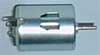 converted perfectly, without any waste. Some energy is wasted as heat
generated by friction of mechanical parts. Inefficiencies
are minimized in well-designed (and more expensive) motors, and their
performance can be brought up to the 90th percentile, but cheap motors
(such as the ones you may use) can be as low as 50%. (In case you
think this is very inefficient, remember that other types of
effectors, such as miniature electrostatic motors, may have much lower
efficiencies still.) A motor requires a power source within its
operating voltage, i.e., the recommended voltage range for best
efficiency of the motor. Lower voltages will usually turn the motor
(but provide less power). Higher voltages are more tricky: in some
cases they can increase the power output but almost always at the
expense of the operating life of the motor. E.g., the more you rev
your car engine, the sooner it will die. When constant voltage is
applied, a DC motor draws current in the amount proportional to
the work it is doing. For example, if a robot is pushing against
a wall, it is drawing more current (and draining more of its
batteries) than when it is moving freely in open space.
converted perfectly, without any waste. Some energy is wasted as heat
generated by friction of mechanical parts. Inefficiencies
are minimized in well-designed (and more expensive) motors, and their
performance can be brought up to the 90th percentile, but cheap motors
(such as the ones you may use) can be as low as 50%. (In case you
think this is very inefficient, remember that other types of
effectors, such as miniature electrostatic motors, may have much lower
efficiencies still.) A motor requires a power source within its
operating voltage, i.e., the recommended voltage range for best
efficiency of the motor. Lower voltages will usually turn the motor
(but provide less power). Higher voltages are more tricky: in some
cases they can increase the power output but almost always at the
expense of the operating life of the motor. E.g., the more you rev
your car engine, the sooner it will die. When constant voltage is
applied, a DC motor draws current in the amount proportional to
the work it is doing. For example, if a robot is pushing against
a wall, it is drawing more current (and draining more of its
batteries) than when it is moving freely in open space.
The reason is the resistance to
the motor motion introduced by the wall. If the resistance is very
high (i.e., the wall just won't move no matter how much the robot
pushes against it), the motor draws a maximum amount of power, and
stalls. This is defined as the stall current of the motor:
the most current it can draw at its specified voltage. Within a
motor's operating current range, the more current is used,
the more torque or rotational force is produced at
the shaft. In general, the strengths of the magnetic field generated
in the wire loops is directly proportional to the applied current and
thus the produced torque at the shaft. Besides stall current, a motor
also has its stall torque, the amount of rotational force
produced when the motor is stalled at its operating voltage. Finally,
the amount of power a motor generates is the product of its
shaft's rotational velocity and its torque. If there
is no load on the shaft, i.e., the motor is spinning freely, then the
rotational velocity is the highest, but the torque is 0, since no
mechanism is being driven by the motor. The output power, then, is 0
also. In contrast, when the motor is stalled, it is producing maximum
torque, but the rotational velocity is 0, so the output power is 0
again.
Between free spinning and
stalling, the motor does useful work, and the produced power has a
characteristic parabolic relationship demonstrating that the motor
produces the most power in the middle of its performance range. Most
DC motors have unloaded speeds in the range of 3,000 to 9,000 RPM
(revolutions per minute), or 50 to 150 RPS (revolutions per second).
That turns out to put them in the high-speed but low-torque category
(compared to some other alternatives). For example, how often do you
need to drive something very light that rotates very fast (besides a
fan)? Yet that is what DC motors are naturally best at. In contrast,
robots need to pull loads (i.e., move their bodies and manipulators,
all of which have significant mass), thus requiring more torque and
less speed. As a result, the performance of a DC motor typically needs
to be adjusted in that direction, through the use of gears.
The force generated at the edge
of a gear is equal to the product of the radius of the gear and its
torque (F = r t), in the line tangential to its circumference. By
combining gears with different radii, we can manipulate the amount of
force/torque the mechanism generates. The relationship between the
radii and the resulting torque is well defined, as follows: Suppose
Gear1 with radius r1 turns with torque t1, generating a force of t1/r1
perpendicular to its circumference. Now if we mesh it with Gear2, with
r2, which generates t2/r2, then t1/r1 = t2/r2. To get the torque
generated by Gear2, we get: t2 = t1 r2/r1. Intuitively, this means:
the torque generated at the output gear is proportional to the torque
on the input gear and the ratio of the two gear's radii. If r2 > r1,
we get a bigger number, if r1 > r2, we get a smaller number.
If the output gear is larger
than the input gear, the torque increases. If the output gear is
smaller than the input gear, the torque decreases. Besides the change
in torque that takes place when gears are combined, there is also a
corresponding change in speed. To measure speed we are interested in
the circumference of the gear, C= 2 * pi * r. Simply put, if the
circumference of Gear1 is twice that of Gear2, then Gear2 must turn
twice for each full rotation of Gear1. If the output gear is larger
than the input gear, the speed decreases. If the output gear is
smaller than the input gear, the speed increases. In summary, when a
small gear drives a large one, torque is increased and speed is
decreased. Analogously, when a large gear drives a small one, torque
is decreased and speed is increased. Thus, gears are used in DC motors
(which we said are fast and low torque) to trade off extra speed for
additional torque. Gears are combined using their teeth. The number
of teeth is not arbitrary, since it is the key means of proper
reduction. Gear teeth require special design so that they mesh
properly. If there is any looseness between meshing gears, this is
called backlash, the ability for a mechanism to move back \&
forth within the teeth, without turning the whole gear.
Reducing backlash requires tight
meshing between the gear teeth, but that, in turn, increases
friction. As you can imagine, proper gear design and
manufacturing is complicated. To achieve "three to one gear reduction
(3:1)", we apply power to a small gear (say one with 8-teeth) meshed
with a large one (with 3 * 8 = 24 teeth). As a result, we have slowed
down the large gear by 3 and have tripled its torque. Gears can be
organized in series ("ganged"), in order to multiply their effect. For
example, 2 3:1 gears in series result in a 9:1 reduction. This
requires a clever arrangement of gears. Or three 3:1 gears in series
can produce a 27:1 reduction. This method of multiplying reduction is
the underlying mechanism that makes DC motors useful and ubiquitous.
It should come as no surprise
that motors require more battery power (i.e., more current) than
electronics (e.g., 5 milliamps for the 68HC11 processor v. 100
milliamps - 1 amp for a small DC motor). Typically, specialized
circuitry is required. You need to learn about H-bridges and
pulse-width modulation there.
It is sometimes necessary to be
able to move a motor to a specific position. If you consider your
basic DC motor, it is not built for this purpose. Motors that can turn
to a specific position are called servo motors and are in
fact constructed out of basic DC motors, by adding:
Servos are used in toys a great
deal, to adjust steering on steering in RC cars and wing position in
RC airplanes. Since positioning of the shaft is what servo motors are all about,
most have their movement reduced to 180 degrees. The motor is driven
with a waveform that specifies the desired angular position of the
shaft within that range. The waveform is given as a series of pulses,
within a pulse-width modulatedsignal. Thus, the width (i.e.,
length) of the pulse specifies the control value for the motor, i.e.,
how the shaft should turn. Therefore, the exact width/length of the
pulse is critical, and cannot be sloppy. There are no milliseconds or
even microseconds to be wasted here, or the motor will behave very
badly, jitter, and go beyond its mechanical limit. This limit should
be checked empirically, and avoided. In contrast, the duration
between the pulses is not critical at all. It should be consistent,
but there can be noise on the order of milliseconds without any
problems for the motor. This is intuitive: when no pulse arrives, the
motor does not move, so it simply stops. As long as the pulse gives
the motor sufficient time to turn to the proper position, additional
time does not hurt it.
Since positioning of the shaft is what servo motors are all about,
most have their movement reduced to 180 degrees. The motor is driven
with a waveform that specifies the desired angular position of the
shaft within that range. The waveform is given as a series of pulses,
within a pulse-width modulatedsignal. Thus, the width (i.e.,
length) of the pulse specifies the control value for the motor, i.e.,
how the shaft should turn. Therefore, the exact width/length of the
pulse is critical, and cannot be sloppy. There are no milliseconds or
even microseconds to be wasted here, or the motor will behave very
badly, jitter, and go beyond its mechanical limit. This limit should
be checked empirically, and avoided. In contrast, the duration
between the pulses is not critical at all. It should be consistent,
but there can be noise on the order of milliseconds without any
problems for the motor. This is intuitive: when no pulse arrives, the
motor does not move, so it simply stops. As long as the pulse gives
the motor sufficient time to turn to the proper position, additional
time does not hurt it.
A regular DC motor can be used
for continuous rotation. Furthermore, servo motors can also be
retrofitted to provide continuous rotation (remember, they only to 180
otherwise), like this:
-
remove mechanical limit (revert back to DC motor shaft)
-
remove pot position sensor (no need to tell position)
-
apply 2 resistors to fool the servo to think it is fully turning
Research into shape memory
alloys, polymer gels and micro-mechanism devices is ongoing, and
changing often. Nickel-titanium alloys were first discovered by the
Naval Ordinance Laboratory decades ago and the material was termed
NiTinOL. These materials have the intriguing property that they
provide actuation through cycling of current through the materials. It
undergoes a �phase change� exhibited as force and motion in the wire.
At room temperature Muscle Wires are easily stretched by a small
force. However, when conducting an electric current, the wire heats
and changes to a much harder form that returns to the "unstretched"
shape -- the wire shortens in length with a usable amount of force.
Nitinol can be stretched by up to eight percent of their length and
will recover fully, but only for a few cycles. However when used in
the three to five percent range, Muscle Wires can run for millions of
cycles with very consistent and reliable performance. |


