Conventional versus
electron flow
"The nice thing about standards is that
there are so many of them to choose from."
Andrew S. Tannenbaum, computer science
professor
When Benjamin Franklin made his conjecture
regarding the direction of charge flow (from the smooth wax
to the rough wool), he set a precedent for electrical
notation that exists to this day, despite the fact that we
know electrons are the constituent units of charge, and that
they are displaced from the wool to the wax -- not from the
wax to the wool -- when those two substances are rubbed
together. This is why electrons are said to have a
negative charge: because Franklin assumed electric
charge moved in the opposite direction that it actually
does, and so objects he called "negative" (representing a
deficiency of charge) actually have a surplus of electrons.
By the time the true direction of electron
flow was discovered, the nomenclature of "positive" and
"negative" had already been so well established in the
scientific community that no effort was made to change it,
although calling electrons "positive" would make more sense
in referring to "excess" charge. You see, the terms
"positive" and "negative" are human inventions, and as such
have no absolute meaning beyond our own conventions of
language and scientific description. Franklin could have
just as easily referred to a surplus of charge as "black"
and a deficiency as "white," in which case scientists would
speak of electrons having a "white" charge (assuming the
same incorrect conjecture of charge position between wax and
wool).
However, because we tend to associate the
word "positive" with "surplus" and "negative" with
"deficiency," the standard label for electron charge does
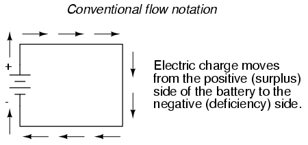
seem backward. Because of this, many engineers decided to
retain the old concept of electricity with "positive"
referring to a surplus of charge, and label charge flow
(current) accordingly. This became known as conventional
flow notation:
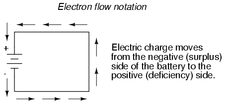
Others chose to designate charge flow
according to the actual motion of electrons in a circuit.
This form of symbology became known as electron flow
notation:
In conventional flow notation, we show the
motion of charge according to the (technically incorrect)
labels of + and -. This way the labels make sense, but the
direction of charge flow is incorrect. In electron flow
notation, we follow the actual motion of electrons in the
circuit, but the + and - labels seem backward. Does it
matter, really, how we designate charge flow in a circuit?
Not really, so long as we're consistent in the use of our
symbols. You may follow an imagined direction of current
(conventional flow) or the actual (electron flow) with equal
success insofar as circuit analysis is concerned. Concepts
of voltage, current, resistance, continuity, and even
mathematical treatments such as Ohm's Law (chapter 2) and
Kirchhoff's Laws (chapter 6) remain just as valid with
either style of notation.
You will find conventional flow notation
followed by most electrical engineers, and illustrated in
most engineering textbooks. Electron flow is most often seen
in introductory textbooks (this one included) and in the
writings of professional scientists, especially solid-state
physicists who are concerned with the actual motion of
electrons in substances. These preferences are cultural, in
the sense that certain groups of people have found it
advantageous to envision electric current motion in certain
ways. Being that most analyses of electric circuits do not
depend on a technically accurate depiction of charge flow,
the choice between conventional flow notation and electron
flow notation is arbitrary . . . almost.
Many electrical devices tolerate real
currents of either direction with no difference in
operation. Incandescent lamps (the type utilizing a thin
metal filament that glows white-hot with sufficient
current), for example, produce light with equal efficiency
regardless of current direction. They even function well on
alternating current (AC), where the direction changes
rapidly over time. Conductors and switches operate
irrespective of current direction, as well. The technical
term for this irrelevance of charge flow is
nonpolarization. We could say then, that incandescent
lamps, switches, and wires are nonpolarized
components. Conversely, any device that functions
differently on currents of different direction would be
called a polarized device.
There are many such polarized devices used
in electric circuits. Most of them are made of so-called
semiconductor substances, and as such aren't examined in
detail until the third volume of this book series. Like
switches, lamps, and batteries, each of these devices is
represented in a schematic diagram by a unique symbol. As
one might guess, polarized device symbols typically contain
an arrow within them, somewhere, to designate a preferred or
exclusive direction of current. This is where the competing
notations of conventional and electron flow really matter.
Because engineers from long ago have settled on conventional
flow as their "culture's" standard notation, and because
engineers are the same people who invent electrical devices
and the symbols representing them, the arrows used in these
devices' symbols all point in the direction of
conventional flow, not electron flow. That is to say,
all of these devices' symbols have arrow marks that point
against the actual flow of electrons through them.
Perhaps the best example of a polarized
device is the diode. A diode is a one-way "valve" for
electric current, analogous to a check valve for
those familiar with plumbing and hydraulic systems. Ideally,
a diode provides unimpeded flow for current in one direction
(little or no resistance), but prevents flow in the other
direction (infinite resistance). Its schematic symbol looks
like this:

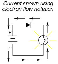
Placed within a battery/lamp circuit, its
operation is as such:
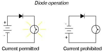
When the diode is facing in the proper
direction to permit current, the lamp glows. Otherwise, the
diode blocks all electron flow just like a break in the
circuit, and the lamp will not glow.
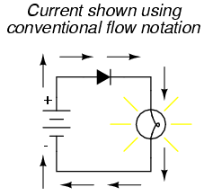
If we label the circuit current using
conventional flow notation, the arrow symbol of the diode
makes perfect sense: the triangular arrowhead points in the
direction of charge flow, from positive to negative:
On the other hand, if we use electron flow
notation to show the true direction of electron
travel around the circuit, the diode's arrow symbology seems
backward:
For this reason alone, many people choose to
make conventional flow their notation of choice when drawing
the direction of charge motion in a circuit. If for no other
reason, the symbols associated with semiconductor components
like diodes make more sense this way. However, others choose
to show the true direction of electron travel so as to avoid
having to tell themselves, "just remember the electrons are
actually moving the other way" whenever the true
direction of electron motion becomes an issue.
In this series of textbooks, I have
committed to using electron flow notation. Ironically, this
was not my first choice. I found it much easier when I was
first learning electronics to use conventional flow
notation, primarily because of the directions of
semiconductor device symbol arrows. Later, when I began my
first formal training in electronics, my instructor insisted
on using electron flow notation in his lectures. In fact, he
asked that we take our textbooks (which were illustrated
using conventional flow notation) and use our pens to change
the directions of all the current arrows so as to point the
"correct" way! His preference was not arbitrary, though. In
his 20-year career as a U.S. Navy electronics technician, he
worked on a lot of vacuum-tube equipment. Before the advent
of semiconductor components like transistors, devices known
as vacuum tubes or electron tubes were used to
amplify small electrical signals. These devices work on the
phenomenon of electrons hurtling through a vacuum, their
rate of flow controlled by voltages applied between metal
plates and grids placed within their path, and are best
understood when visualized using electron flow notation.
When I graduated from that training program,
I went back to my old habit of conventional flow notation,
primarily for the sake of minimizing confusion with
component symbols, since vacuum tubes are all but obsolete
except in special applications. Collecting notes for the
writing of this book, I had full intention of illustrating
it using conventional flow.
Years later, when I became a teacher of
electronics, the curriculum for the program I was going to
teach had already been established around the notation of
electron flow. Oddly enough, this was due in part to the
legacy of my first electronics instructor (the 20-year Navy
veteran), but that's another story entirely! Not wanting to
confuse students by teaching "differently" from the other
instructors, I had to overcome my habit and get used to
visualizing electron flow instead of conventional. Because I
wanted my book to be a useful resource for my students, I
begrudgingly changed plans and illustrated it with all the
arrows pointing the "correct" way. Oh well, sometimes you
just can't win!
On a positive note (no pun intended), I have
subsequently discovered that some students prefer electron
flow notation when first learning about the behavior of
semiconductive substances. Also, the habit of visualizing
electrons flowing against the arrows of polarized
device symbols isn't that difficult to learn, and in the end
I've found that I can follow the operation of a circuit
equally well using either mode of notation. Still, I
sometimes wonder if it would all be much easier if we went
back to the source of the confusion -- Ben Franklin's errant
conjecture -- and fixed the problem there, calling electrons
"positive" and protons "negative."
|
