Resistance
The circuit in the previous section is not a
very practical one. In fact, it can be quite dangerous to
build (directly connecting the poles of a voltage source
together with a single piece of wire). The reason it is
dangerous is because the magnitude of electric current may
be very large in such a short circuit, and the
release of energy very dramatic (usually in the form of
heat). Usually, electric circuits are constructed in such a
way as to make practical use of that released energy, in as
safe a manner as possible.
One practical and popular use of electric
current is for the operation of electric lighting. The
simplest form of electric lamp is a tiny metal "filament"
inside of a clear glass bulb, which glows white-hot
("incandesces") with heat energy when sufficient electric
current passes through it. Like the battery, it has two
conductive connection points, one for electrons to enter and
the other for electrons to exit.
Connected to a source of voltage, an
electric lamp circuit looks something like this:
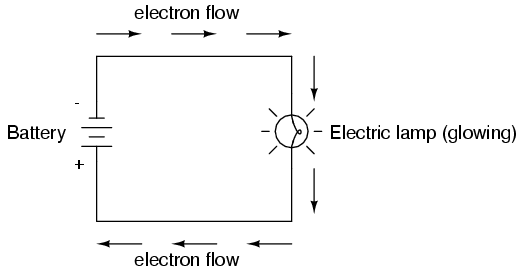
As the electrons work their way through the
thin metal filament of the lamp, they encounter more
opposition to motion than they typically would in a thick
piece of wire. This opposition to electric current depends
on the type of material, its cross-sectional area, and its
temperature. It is technically known as resistance.
(It can be said that conductors have low resistance and
insulators have very high resistance.) This resistance
serves to limit the amount of current through the circuit
with a given amount of voltage supplied by the battery, as
compared with the "short circuit" where we had nothing but a
wire joining one end of the voltage source (battery) to the
other.
When electrons move against the opposition
of resistance, "friction" is generated. Just like mechanical
friction, the friction produced by electrons flowing against
a resistance manifests itself in the form of heat. The
concentrated resistance of a lamp's filament results in a
relatively large amount of heat energy dissipated at that
filament. This heat energy is enough to cause the filament
to glow white-hot, producing light, whereas the wires
connecting the lamp to the battery (which have much lower
resistance) hardly even get warm while conducting the same
amount of current.
As in the case of the short circuit, if the
continuity of the circuit is broken at any point, electron
flow stops throughout the entire circuit. With a lamp in
place, this means that it will stop glowing:
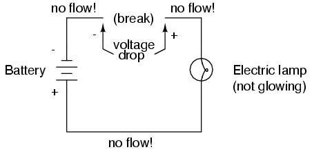
As before, with no flow of electrons, the
entire potential (voltage) of the battery is available
across the break, waiting for the opportunity of a
connection to bridge across that break and permit electron
flow again. This condition is known as an open circuit,
where a break in the continuity of the circuit prevents
current throughout. All it takes is a single break in
continuity to "open" a circuit. Once any breaks have been
connected once again and the continuity of the circuit
re-established, it is known as a closed circuit.
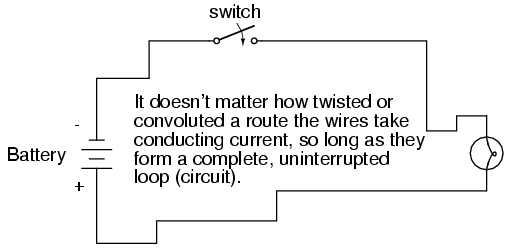
What we see here is the basis for switching
lamps on and off by remote switches. Because any break in a
circuit's continuity results in current stopping throughout
the entire circuit, we can use a device designed to
intentionally break that continuity (called a switch),
mounted at any convenient location that we can run wires to,
to control the flow of electrons in the circuit:
This is how a switch mounted on the wall of
a house can control a lamp that is mounted down a long
hallway, or even in another room, far away from the switch.
The switch itself is constructed of a pair of conductive
contacts (usually made of some kind of metal) forced
together by a mechanical lever actuator or pushbutton. When
the contacts touch each other, electrons are able to flow
from one to the other and the circuit's continuity is
established; when the contacts are separated, electron flow
from one to the other is prevented by the insulation of the
air between, and the circuit's continuity is broken.
Perhaps the best kind of switch to show for
illustration of the basic principle is the "knife" switch:
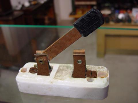
A knife switch is nothing more than a
conductive lever, free to pivot on a hinge, coming into
physical contact with one or more stationary contact points
which are also conductive. The switch shown in the above
illustration is constructed on a porcelain base (an
excellent insulating material), using copper (an excellent
conductor) for the "blade" and contact points. The handle is
plastic to insulate the operator's hand from the conductive
blade of the switch when opening or closing it.
Here is another type of knife switch, with
two stationary contacts instead of one:
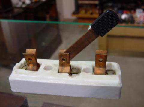
The particular knife switch shown here has
one "blade" but two stationary contacts, meaning that it can
make or break more than one circuit. For now this is not
terribly important to be aware of, just the basic concept of
what a switch is and how it works.
Knife switches are great for illustrating
the basic principle of how a switch works, but they present
distinct safety problems when used in high-power electric
circuits. The exposed conductors in a knife switch make
accidental contact with the circuit a distinct possibility,
and any sparking that may occur between the moving blade and
the stationary contact is free to ignite any nearby
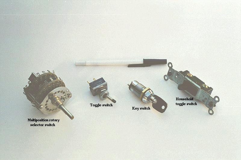
flammable materials. Most modern switch designs have their
moving conductors and contact points sealed inside an
insulating case in order to mitigate these hazards. A
photograph of a few modern switch types show how the
switching mechanisms are much more concealed than with the
knife design:
In keeping with the "open" and "closed"
terminology of circuits, a switch that is making contact
from one connection terminal to the other (example: a knife
switch with the blade fully touching the stationary contact
point) provides continuity for electrons to flow through,
and is called a closed switch. Conversely, a switch
that is breaking continuity (example: a knife switch with
the blade not touching the stationary contact point)
won't allow electrons to pass through and is called an
open switch. This terminology is often confusing to the
new student of electronics, because the words "open" and
"closed" are commonly understood in the context of a door,
where "open" is equated with free passage and "closed" with
blockage. With electrical switches, these terms have
opposite meaning: "open" means no flow while "closed" means
free passage of electrons.
-
REVIEW:
-
Resistance is the measure of
opposition to electric current.
-
A short circuit is an electric
circuit offering little or no resistance to the flow of
electrons. Short circuits are dangerous with high voltage
power sources because the high currents encountered can
cause large amounts of heat energy to be released.
-
An open circuit is one where the
continuity has been broken by an interruption in the path
for electrons to flow.
-
A closed circuit is one that is
complete, with good continuity throughout.
-
A device designed to open or close a
circuit under controlled conditions is called a switch.
-
The terms "open" and "closed"
refer to switches as well as entire circuits. An open
switch is one without continuity: electrons cannot flow
through it. A closed switch is one that provides a direct
(low resistance) path for electrons to flow through.
|
