Commutating diode
PARTS AND MATERIALS
-
6 volt battery
-
Power transformer, 120VAC step-down to
12VAC (Radio Shack catalog # 273-1365, 273-1352, or
273-1511).
-
One 1N4001 rectifying diode (Radio Shack
catalog # 276-1101)
-
One neon lamp (Radio Shack catalog #
272-1102)
-
Two toggle switches, SPST ("Single-Pole,
Single-Throw")
A power transformer is specified, but any
iron-core inductor will suffice, even the home-made inductor
or transformer from the AC experiments chapter!
The diode need not be an exact model 1N4001.
Any of the "1N400X" series of rectifying diodes are suitable
for the task, and they are quite easy to obtain.
I recommend household light switches for
their low cost and durability.
CROSS-REFERENCES
Lessons In Electric Circuits, Volume
1, chapter 16: "RC and L/R Time Constants"
Lessons In Electric Circuits, Volume
3, chapter 3: "Diodes and Rectifiers"
LEARNING OBJECTIVES
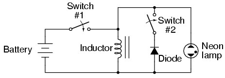
SCHEMATIC DIAGRAM
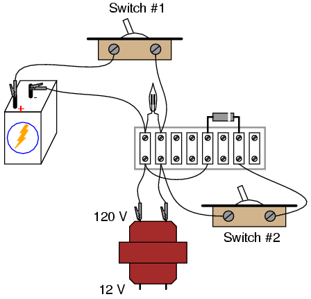
ILLUSTRATION
INSTRUCTIONS
When assembling the circuit, be very careful
of the diode's orientation. The cathode end of the diode
(the end marked with a single band) must face the positive
(+) side of the battery. The diode should be reverse-biased
and nonconducting with switch #1 in the "on" position. Use
the high-voltage (120 V) winding of the transformer for the
inductor coil. The primary winding of a step-down
transformer has more inductance than the secondary winding,
and will give a greater lamp-flashing effect.
Set switch #2 to the "off" position. This
disconnects the diode from the circuit so that it has no
effect. Quickly close and open (turn "on" and then "off")
switch #1. When that switch is opened, the neon bulb will
flash from the effect of inductive "kickback." Rapid current
decrease caused by the switch's opening causes the inductor
to create a large voltage drop as it attempts to keep
current at the same magnitude and going in the same
direction.
Inductive kickback is detrimental to switch
contacts, as it causes excessive arcing whenever they are
opened. In this circuit, the neon lamp actually diminishes
the effect by providing an alternate current path for the
inductor's current when the switch opens, dissipating the
inductor's stored energy harmlessly in the form of light and
heat. However, there is still a fairly high voltage dropped
across the opening contacts of switch #1, causing undue
arcing and shortened switch life.
If switch #2 is closed (turned "on"), the
diode will now be a part of the circuit. Quickly close and
open switch #1 again, noting the difference in circuit
behavior. This time, the neon lamp does not flash. Connect a
voltmeter across the inductor to verify that the inductor is
still receiving full battery voltage with switch #1 closed.
If the voltmeter registers only a small voltage with switch
#1 "on," the diode is probably connected backward, creating
a short-circuit.
|
