Half-wave rectifier
PARTS AND MATERIALS
-
Low-voltage AC power supply (6 volt
output)
-
6 volt battery
-
One 1N4001 rectifying diode (Radio Shack
catalog # 276-1101)
-
Small "hobby" motor, permanent-magnet type
(Radio Shack catalog # 273-223 or equivalent)
-
Audio detector with headphones
-
0.1 �F capacitor (Radio Shack catalog #
272-135 or equivalent)
The diode need not be an exact model 1N4001.
Any of the "1N400X" series of rectifying diodes are suitable
for the task, and they are quite easy to obtain.
See the AC experiments chapter for detailed
instructions on building the "audio detector" listed here.
If you haven't built one already, you're missing a simple
and valuable tool for experimentation.
A 0.1 �F capacitor is specified for
"coupling" the audio detector to the circuit, so that only
AC reaches the detector circuit. This capacitor's value is
not critical. I've used capacitors ranging from 0.27 �F to
0.015 �F with success. Lower capacitor values attenuate
low-frequency signals to a greater degree, resulting in less
sound intensity from the headphones, so use a greater-value
capacitor value if you experience difficulty hearing the
tone(s).
CROSS-REFERENCES
Lessons In Electric Circuits, Volume
3, chapter 3: "Diodes and Rectifiers"
LEARNING OBJECTIVES
-
Function of a diode as a rectifier
-
Permanent-magnet motor operation on AC
versus DC power
-
Measuring "ripple" voltage with a
voltmeter
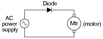
SCHEMATIC DIAGRAM
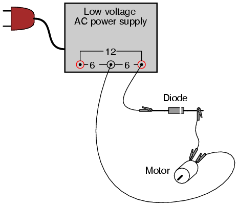
ILLUSTRATION
INSTRUCTIONS
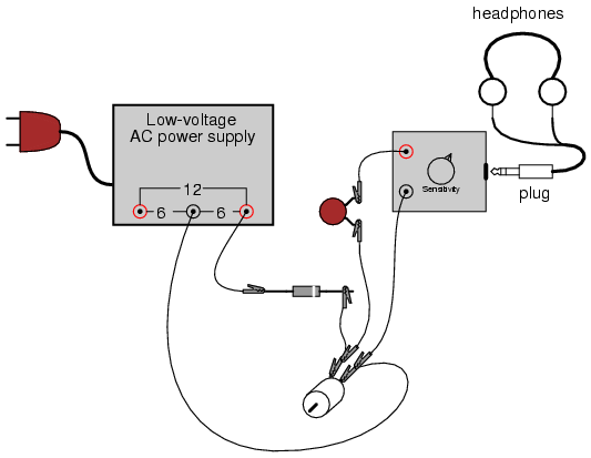
Connect the motor to the low-voltage AC
power supply through the rectifying diode as shown. The
diode only allows current to pass through during one
half-cycle of a full positive-and-negative cycle of power
supply voltage, eliminating one half-cycle from ever
reaching the motor. As a result, the motor only "sees"
current in one direction, albeit a pulsating current,
allowing it to spin in one direction.
Take a jumper wire and short past the diode
momentarily, noting the effect on the motor's operation:
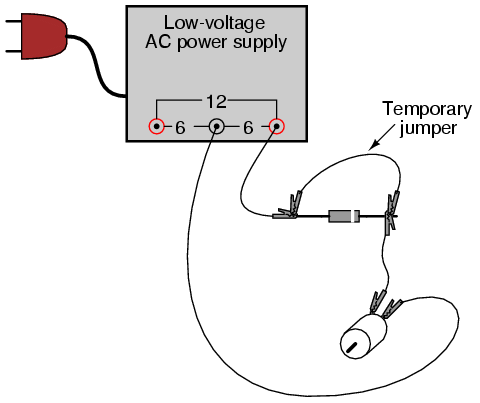
As you can see, permanent-magnet "DC" motors do not function
well on alternating current. Remove the temporary jumper
wire and reverse the diode's orientation in the circuit.
Note the effect on the motor.
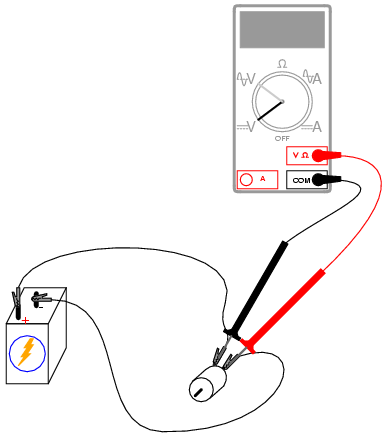
Measure DC voltage across the motor like
this:
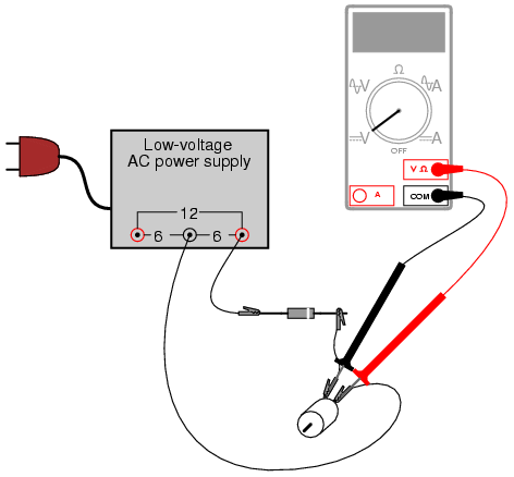
Then, measure AC voltage across the motor as
well:

Most digital multimeters do a good job of
discriminating AC from DC voltage, and these two
measurements show the DC average and AC "ripple" voltages,
respectively of the power "seen" by the motor. Ripple
voltage is the varying portion of the voltage,
interpreted as an AC quantity by measurement equipment
although the voltage waveform never actually reverses
polarity. Ripple may be envisioned as an AC signal
superimposed on a steady DC "bias" or "offset" signal.
Compare these measurements of DC and AC with voltage
measurements taken across the motor while powered by a
battery:
Batteries give very "pure" DC power, and as
a result there should be very little AC voltage measured
across the motor in this circuit. Whatever AC voltage is
measured across the motor is due to the motor's pulsating
current draw as the brushes make and break contact with the
rotating commutator bars. This pulsating current causes
pulsating voltages to be dropped across any stray
resistances in the circuit, resulting in pulsating voltage
"dips" at the motor terminals.
A qualitative assessment of ripple voltage
may be obtained by using the sensitive audio detector
described in the AC experiments chapter (the same device
described as a "sensitive voltage detector" in the DC
experiments chapter). Turn the detector's sensitivity down
for low volume, and connect it across the motor terminals
through a small (0.1 �F) capacitor, like this:
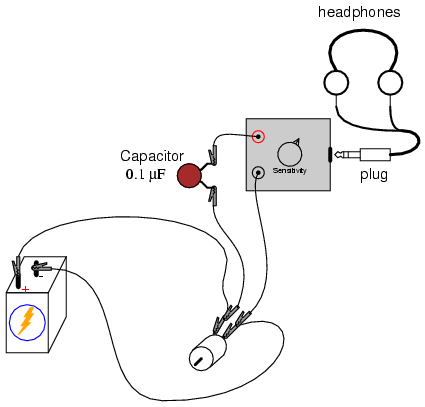
The capacitor acts as a high-pass filter,
blocking DC voltage from reaching the detector and allowing
easier "listening" of the remaining AC voltage. This is the
exact same technique used in oscilloscope circuitry for "AC
coupling," where DC signals are blocked from viewing by a
series-connected capacitor. With a battery powering the
motor, the ripple should sound like a high-pitched "buzz" or
"whine." Try replacing the battery with the AC power supply
and rectifying diode, "listening" with the detector to the
low-pitched "buzz" of the half-wave rectified power:
COMPUTER SIMULATION
Schematic with SPICE node numbers:
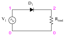
Netlist (make a text file containing the
following text, verbatim):
Halfwave rectifier
v1 1 0 sin(0 8.485 60 0 0)
rload 2 0 10k
d1 1 2 mod1
.model mod1 d
.tran .5m 25m
.plot tran v(1,0) v(2,0)
.end
This simulation plots the input voltage as a
sine wave and the output voltage as a series of "humps"
corresponding to the positive half-cycles of the AC source
voltage. The dynamics of a DC motor are far too complex to
be simulated using SPICE, unfortunately.
AC source voltage is specified as 8.485
instead of 6 volts because SPICE understands AC voltage in
terms of peak value only. A 6 volt RMS sine-wave
voltage is actually 8.485 volts peak. In simulations where
the distinction between RMS and peak value isn't relevant, I
will not bother with an RMS-to-peak conversion like this. To
be truthful, the distinction is not terribly important in
this simulation, but I discuss it here for your edification. |
