Static electricity sensor
PARTS AND MATERIALS
-
One N-channel junction field-effect
transistor, models 2N3819 or J309 recommended (Radio Shack
catalog # 276-2035 is the model 2N3819)
-
One 6 volt battery
-
One 100 kΩ resistor
-
One light-emitting diode (Radio Shack
catalog # 276-026 or equivalent)
-
Plastic comb
The particular junction field-effect
transistor, or JFET, model used in this experiment is not
critical. P-channel JFETs are also okay to use, but are not
as popular as N-channel transistors.
Beware that not all transistors share the
same terminal designations, or pinouts, even if they
share the same physical appearance. This will dictate how
you connect the transistors together and to other
components, so be sure to check the manufacturer's
specifications (component datasheet), easily obtained from
the manufacturer's website. Beware that it is possible for
the transistor's package and even the manufacturer's
datasheet to show incorrect terminal identification
diagrams! Double-checking pin identities with your
multimeter's "diode check" function is highly recommended.
For details on how to identify junction field-effect
transistor terminals using a multimeter, consult chapter 5
of the Semiconductor volume (volume III) of this book
series.
CROSS-REFERENCES
Lessons In Electric Circuits, Volume
3, chapter 5: "Junction Field-Effect Transistors"
LEARNING OBJECTIVES
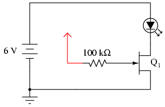
SCHEMATIC DIAGRAM
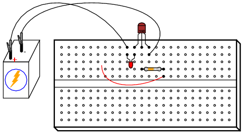
ILLUSTRATION
INSTRUCTIONS
This experiment is very similar to the
previous experiment using a bipolar junction transistor (BJT)
as a switching device to control current through an LED. In
this experiment, a junction field-effect transistor
is used instead, giving dramatically improved sensitivity.
Build this circuit and touch the loose wire
end (the wire shown in red on the schematic diagram and in
the illustration, connected to the 100 kΩ resistor) with
your hand. Simply touching this wire will likely have an
effect on the LED's status. This circuit makes a fine sensor
of static electricity! Try scuffing your feet on a carpet
and then touching the wire end if no effect on the light is
seen yet.
For a more controlled test, touch the wire
with one hand and alternately touch the positive (+) and
negative (-) terminals of the battery with one finger of
your other hand. Your body acts as a conductor (albeit a
poor one), connecting the gate terminal of the JFET to
either terminal of the battery as you touch them. Make note
which terminal makes the LED turn on and which makes the LED
turn off. Try to relate this behavior with what you've read
about JFETs in chapter 5 of the Semiconductor volume.
The fact that a JFET is turned on and off so
easily (requiring so little control current), as evidenced
by full on-and-off control simply by conduction of a control
current through your body, demonstrates how great of a
current gain it has. With the BJT "switch" experiment, a
much more "solid" connection between the transistor's gate
terminal and a source of voltage was needed to turn it on.
Not so with the JFET. In fact, the mere presence of static
electricity can turn it on and off at a distance.
To further experiment with the effects of
static electricity on this circuit, brush your hair with the
plastic comb and then wave the comb near the transistor,
watching the effect on the LED. The action of combing your
hair with a plastic object creates a high static voltage
between the comb and your body. The strong electric field
produced between these two objects should be detectable by
this circuit from a significant distance!
In case you're wondering why there is no 560
Ω "dropping" resistor to limit current through the LED, many
small-signal JFETs tend to self-limit their controlled
current to a level acceptable by LEDs. The model 2N3819, for
example, has a typical saturated drain current (IDSS)
of 10 mA and a maximum of 20 mA. Since most LEDs are rated
at a forward current of 20 mA, there is no need for a
dropping resistor to limit circuit current: the JFET does it
intrinsically.
|
