Full-wave bridge rectifier
PARTS AND MATERIALS
-
Low-voltage AC power supply (6 volt
output)
-
Four 1N4001 rectifying diodes (Radio Shack
catalog # 276-1101)
-
Small "hobby" motor, permanent-magnet type
(Radio Shack catalog # 273-223 or equivalent)
CROSS-REFERENCES
Lessons In Electric Circuits, Volume
3, chapter 3: "Diodes and Rectifiers"
LEARNING OBJECTIVES
-
Design of a bridge rectifier circuit
-
Advantages and disadvantages of the bridge
rectifier circuit, compared to the center-tap circuit
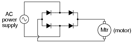
SCHEMATIC DIAGRAM
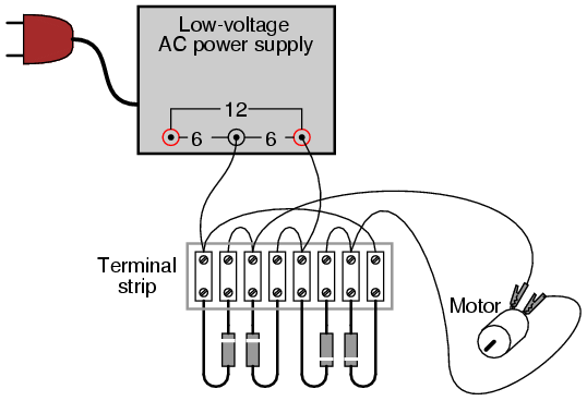
ILLUSTRATION
INSTRUCTIONS
This circuit provides full-wave
rectification without the necessity of a center-tapped
transformer. In applications where a center-tapped, or
split-phase, source is unavailable, this is the only
practical method of full-wave rectification.
In addition to requiring more diodes than
the center-tap circuit, the full-wave bridge suffers a
slight performance disadvantage as well: the additional
voltage drop caused by current having to go through two
diodes in each half-cycle rather than through only one. With
a low-voltage source such as the one you're using (6 volts
RMS), this disadvantage is easily measured. Compare the DC
voltage reading across the motor terminals with the reading
obtained from the last experiment, given the same AC power
supply and the same motor.
COMPUTER SIMULATION
Schematic with SPICE node numbers:
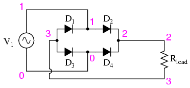
Netlist (make a text file containing the
following text, verbatim):
Fullwave bridge rectifier
v1 1 0 sin(0 8.485 60 0 0)
rload 2 3 10k
d1 3 1 mod1
d2 1 2 mod1
d3 3 0 mod1
d4 0 2 mod1
.model mod1 d
.tran .5m 25m
.plot tran v(1,0) v(2,3)
.end
|
